h ig h ot f oor
rfmo
The arm of the TRAV’LER antenna extends 33” from the center of the base and may operate only 10” above the” 5.7 surface to which the TRAV’LER antenna is mounted. To ensure you have adequate clearance for the TRAV’LER3
antenna to safely operate, check that there are no obstructions taller than 10” within 33” of the center of the base. Also, check that there are no obstructions (such as tree limbs) above the antenna that will prevent it from raising. At its highest point, the antenna will extend to 37.5” above the roof to which it is mounted. See Figure 2.
Choosing a Location for the TRAV’LER Antenna
For best performance and to reduce signal acquisition time, park the vehicle on a level surface that is free of obstructions such as trees or large buildings. Make sure you have a clear view of the southern sky.
Before removing the TRAV’LER antenna from its box, contact your RV dealer or manufacturer. Your RV may be
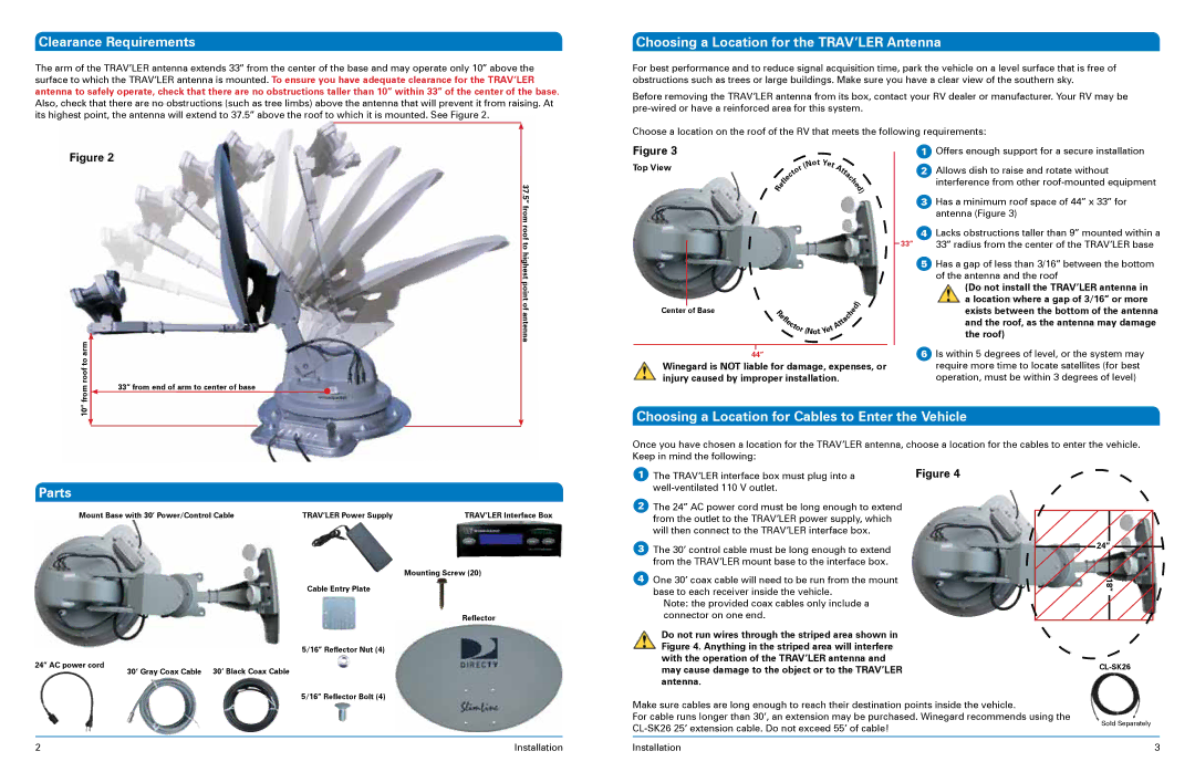
Choose a location on the roof of the RV that meets the following requirements:
Figure 2
Figure 3
Top View
Center of Base
|
|
|
|
|
|
| ot Y |
|
|
| |
|
|
|
|
|
| N | e |
|
| ||
|
|
|
|
| ( |
|
| t | A |
| |
|
|
|
| r |
|
|
|
|
| ||
|
|
| o |
|
|
|
|
| t | ||
|
|
| t |
|
|
|
|
|
|
| t |
|
| c |
|
|
|
|
|
|
| a | |
|
| le |
|
|
|
|
|
|
|
| h |
| f |
|
|
|
|
|
|
|
| c | |
|
|
|
|
|
|
|
|
| e | ||
R | e |
|
|
|
|
|
|
|
|
| d |
|
|
|
|
|
|
|
|
|
| ) | |
|
|
|
|
|
|
|
|
|
|
| |
|
|
|
|
|
|
|
|
|
| e | d | ) |
R |
|
|
|
|
|
|
|
| h |
| ||
|
|
|
|
|
|
|
|
|
| |||
e |
|
|
|
|
|
|
|
|
|
|
| |
f |
|
|
|
|
|
|
| c |
|
|
| |
l |
|
|
|
|
|
| a |
|
|
|
| |
e |
|
|
|
|
| t |
|
|
|
| ||
c |
|
|
|
| t |
|
|
|
|
| ||
|
|
| A |
|
|
|
|
|
| |||
| t |
|
|
|
|
|
|
|
|
| ||
| o |
| t |
|
|
|
|
|
|
| ||
|
| r | e |
|
|
|
|
|
|
|
| |
|
|
| (NotY |
|
|
|
|
|
|
|
|
|
1Offers enough support for a secure installation
2Allows dish to raise and rotate without interference from other
3Has a minimum roof space of 44” x 33” for antenna (Figure 3)
4Lacks obstructions taller than 9” mounted within a
33” | 33” radius from the center of the TRAV’LER base |
5Has a gap of less than 3/16” between the bottom of the antenna and the roof
(Do not install the TRAV’LER antenna in a location where a gap of 3/16” or more exists between the bottom of the antenna and the roof, as the antenna may damage the roof)
roof to arm | 33” from end of arm to center of base | |
10” from | ||
| ||
|
|
|
| 6 Is within 5 degrees of level, or the system may |
44” | ||
Winegard is NOT liable for damage, expenses, or | require more time to locate satellites (for best | |
injury caused by improper installation. | operation, must be within 3 degrees of level) | |
Choosing a Location for Cables to Enter the Vehicle
Once you have chosen a location for the TRAV’LER antenna, choose a location for the cables to enter the vehicle. Keep in mind the following:
Parts
Mount Base with 30’ Power/Control Cable | TRAV’LER Power Supply | TRAV’LER Interface Box |
Mounting Screw (20)
Cable Entry Plate
Reflector
1 The TRAV’LER interface box must plug into a | Figure 4 |
|
2The 24” AC power cord must be long enough to extend from the outlet to the TRAV’LER power supply, which will then connect to the TRAV’LER interface box.
3The 30’ control cable must be long enough to extend from the TRAV’LER mount base to the interface box.
4One 30’ coax cable will need to be run from the mount base to each receiver inside the vehicle.
Note: the provided coax cables only include a connector on one end.
24” |
18” |
5/16” Reflector Nut (4)
24” AC power cord | 30’ Gray Coax Cable | 30’ Black Coax Cable |
|
5/16” Reflector Bolt (4)
2 | Installation |
Do not run wires through the striped area shown in Figure 4. Anything in the striped area will interfere with the operation of the TRAV’LER antenna and may cause damage to the object or to the TRAV’LER antenna.
Make sure cables are long enough to reach their destination points inside the vehicle.
For cable runs longer than 30’, an extension may be purchased. Winegard recommends using the
Installation
Sold Separately
3