ASSEMBLED VIEW
FIGURE 13
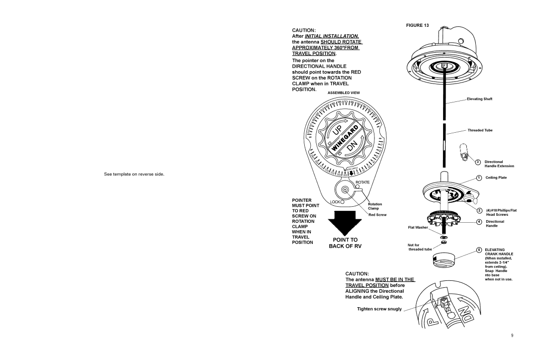
CAUTION:
After INITIAL INSTALLATION, the antenna SHOULD ROTATE APPROXIMATELY 360°FROM
TRAVEL POSITION.
The pointer on the
DIRECTIONAL HANDLE should point towards the RED SCREW on the ROTATION CLAMP when in TRAVEL POSITION.
Elevating Shaft
See template on reverse side.
240![]()
![]()
![]()
250
290
300 |
|
|
|
310 | 320 |
|
|
| 330 |
| |
|
| 340 | |
|
|
|
NORTH ![]() 350
350![]()
POINT ![]()
![]() 10
10
20
![]()
![]() 70
70 ![]()
![]()
![]() 60
60
![]()
![]() 50
50
![]()
![]() 40
40
30
Threaded Tube
![]() 3 Directional Handle Extension
3 Directional Handle Extension
1 Ceiling Plate
POINTER MUST POINT TO RED SCREW ON ROTATION CLAMP WHEN IN TRAVEL POSITION
Rotation
Clamp
Red Screw
Flat Washer
POINT TO
BACK OF RVNut for
threaded tube
CAUTION:
The antenna MUST BE IN THE
TRAVEL POSITION before
ALIGNING the Directional
Handle and Ceiling Plate.
Tighten screw snugly 

2 (4) #10 Phillips Flat
Head Screws
4 | Directional |
| Handle |
5ELEVATING CRANK HANDLE (When installed, extends
when not in use.
9