Planning Information
Model CTWH36 Cooktop Wall Hood
| (E) UPPER FLUE TOTAL | ||
| HEIGHT TO CEILING | ||
| (F) |
|
|
| MAXIMUM |
|
|
| HEIGHT OF |
| (D) |
| HOOD | BOTTOM | |
|
| ||
| OF HOOD TO | ||
| MINIMUM FLUE | ||
| EXTENSION | ||
(A) |
|
|
|
TOTAL |
|
|
|
FLOOR TO |
|
| |
CEILING |
|
| |
HEIGHT | (C) |
|
|
| COUNTERTOP |
| |
| TO BOTTOM |
|
|
| OF HOOD |
|
|
| (B) |
|
|
| FLOOR TO |
|
|
| COUNTERTOP |
| |
| HEIGHT |
|
|
C O O K T O P H O O D P L A C E M E N T
Wolf cooktop wall ventilation hoods come with a telescopic chimney flue that allows you to reach a ceiling height of 8' (2.4 m) to 9' (2.7 m) with a finished look. A flue extension to accommo- date 10' (3 m) ceilings is available as a sales accessory.
Installation of the wall hood should be 24" (610) to 30" (762) from the bottom of the hood to the countertop.
IMPORTANT NOTE: 8' (2.4 m) ceilings will not allow for a 30"
(762)maximum height above the countertop. Based on a 36"
(914)high countertop, an 8' (2.4 m) ceiling will allow for a maximum height above the countertop of 275/16" (694).
IMPORTANT NOTE: Both sections of the telescopic chimney flue must be installed in order for the chimney to be lifted for service.
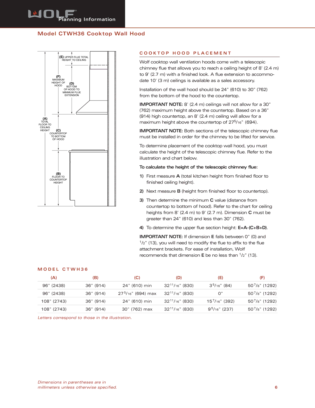
To determine placement of the cooktop wall hood, you must calculate the height of the telescopic chimney flue. Refer to the illustration and chart below.
To calculate the height of the telescopic chimney flue:
1)First measure A (total kitchen height from finished floor to finished ceiling height).
2)Next measure B (height from finished floor to countertop).
3)Then determine the minimum C value (distance from countertop to bottom of hood). Refer to the chart for ceiling heights from 8' (2.4 m) to 9' (2.7 m). Dimension C must be greater than 24" (610) and less than 30" (762).
4)To determine the upper flue section height:
IMPORTANT NOTE: If dimension E falls between 0" (0) and 1/2" (13), you will need to modify the flue to affix to the flue attachment brackets. For ease of installation, Wolf recommends that dimension E be no less than 1/2" (13).
M O D E L C T W H 3 6 |
|
|
|
|
| |
(A) | (B) | (C) | (D) | (E) |
| (F) |
|
|
|
|
|
|
|
96" (2438) | 36" (914) | 24" (610) min | 3211/16" (830) | 3 5/16" | (84) | 50 7/8" (1292) |
96" (2438) | 36" (914) | 27 5/16" (694) max | 3211/16" (830) | 0" |
| 50 7/8" (1292) |
108" (2743) | 36" (914) | 24" (610) min | 3211/16" (830) | 15 7/16" | (392) | 50 7/8" (1292) |
108" (2743) | 36" (914) | 30" (762) max | 3211/16" (830) | 9 5/16" (237) | 50 7/8" (1292) | |
Letters correspond to those in the illustration.
Dimensions in parentheses are in |
|
millimeters unless otherwise specified. | 6 |
