Sub-Frame Fit-Up
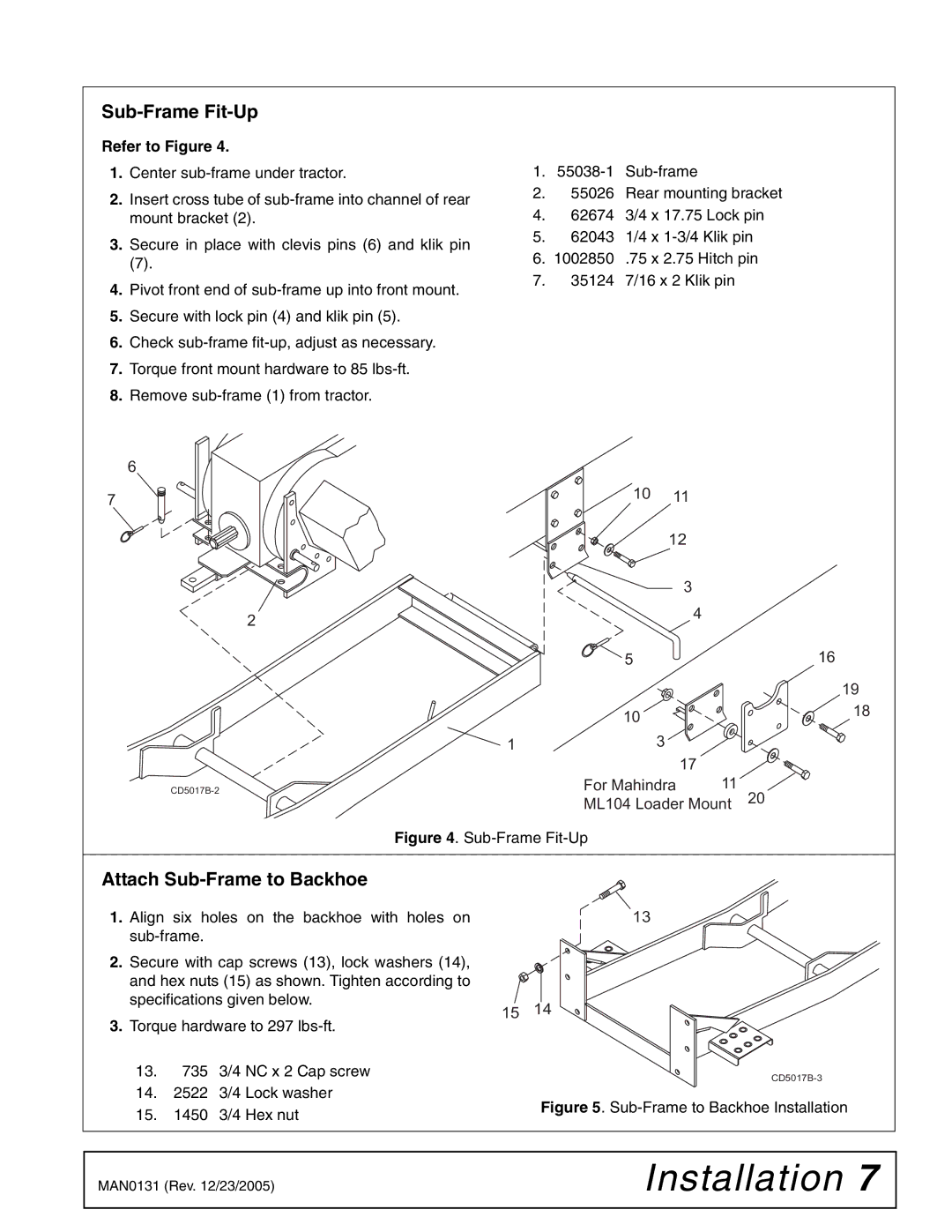
Refer to Figure 4.
1.Center
2.Insert cross tube of
3.Secure in place with clevis pins (6) and klik pin
(7).
4.Pivot front end of
5.Secure with lock pin (4) and klik pin (5).
6.Check
7.Torque front mount hardware to 85
8.Remove
1.
2.55026 Rear mounting bracket
4.62674 3/4 x 17.75 Lock pin
5.62043 1/4 x
6.1002850 .75 x 2.75 Hitch pin
7.35124 7/16 x 2 Klik pin
6 |
|
|
|
|
7 | 10 | 11 |
|
|
|
| 12 |
|
|
|
| 3 |
|
|
2 |
| 4 |
|
|
|
|
|
| |
| 5 |
|
| 16 |
|
|
|
| 19 |
| 10 |
|
| 18 |
|
|
|
| |
1 |
| 3 |
|
|
|
| 17 | 11 |
|
For Mahindra | 20 | |||
| ML104 Loader Mount | |||
Figure 4. Sub-Frame Fit-Up
Attach Sub-Frame to Backhoe
1.Align six holes on the backhoe with holes on
2.Secure with cap screws (13), lock washers (14), and hex nuts (15) as shown. Tighten according to specifications given below.
3.Torque hardware to 297
13.735 3/4 NC x 2 Cap screw
14.2522 3/4 Lock washer
15.1450 3/4 Hex nut
| 13 |
15 | 14 |
|
Figure 5. Sub-Frame to Backhoe Installation
MAN0131 (Rev. 12/23/2005) | Installation 7 |
|
|