To provide necessary balance, loader frame must be equipped with bucket or attachment before attaching or detaching from tractor, or when loader is in stored position.
Do not climb or lean on equipment stored on stand.
![]() CAUTION
CAUTION
Keep children and bystanders away from stor- age area.
CONNECT LOADER SUPPLY HOSES TO LOADER
Refer to Loader Mounting Kit Manual for hose kit instal- lation.
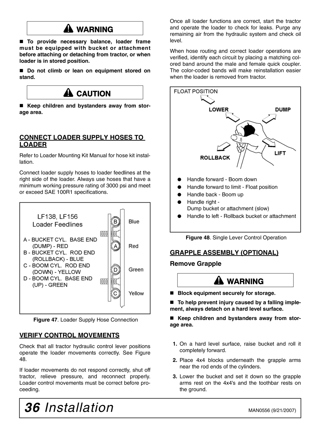
Connect loader supply hoses to loader feedlines at the right side of the loader. Always use hoses that have a minimum working pressure rating of 3000 psi and meet or exceed SAE 100R1 specifications.
Figure 47. Loader Supply Hose Connection
VERIFY CONTROL MOVEMENTS
Check that all tractor hydraulic control lever positions operate the loader movements correctly. See Figure 48.
If loader movements do not respond correctly, shut off tractor, relieve pressure, and reconnect properly. Loader control movements must be correct before pro- ceeding.
Once all loader functions are correct, start the tractor and operate the loader to check for leaks. Purge any remaining air from the hydraulic system and check oil level.
When hose routing and correct loader operations are verified, identify each circuit by placing a matching col- ored band around the male and female quick coupler. The
●Handle forward - Boom down
●Handle forward to limit - Float position
●Handle back - Boom up
●Handle right -
Dump bucket or attachment (slow)
●Handle to left - Rollback bucket or attachment
Figure 48. Single Lever Control Operation
GRAPPLE ASSEMBLY (OPTIONAL)
Remove Grapple
Block equipment securely for storage.
To help prevent injury caused by a falling imple- ment, always detach on a hard level surface.
Keep children and bystanders away from stor- age area.
1.On a hard level surface, raise bucket and roll it completely forward.
2.Place 4x4 blocks underneath the grapple arms near the rod ends of the cylinders.
3.Lower the bucket and set it down so the grapple arms rest on the 4x4's and the toothbar rests on the ground.
36 Installation | MAN0556 (9/21/2007) |
|
|
