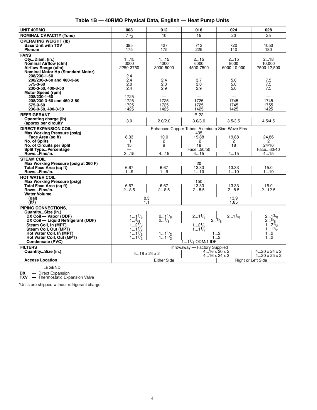
Table 1B — 40RMQ Physical Data, English — Heat Pump Units
UNIT 40RMQ | 008 |
|
|
| 012 |
|
| 016 |
|
| 024 |
| 028 |
|
NOMINAL CAPACITY (Tons) | 71/2 |
|
|
| 10 |
|
| 15 |
|
| 20 |
| 25 |
|
OPERATING WEIGHT (lb) |
|
|
|
|
|
|
|
|
|
|
|
|
|
|
Base Unit with TXV | 385 |
|
|
| 427 |
|
| 713 |
|
| 720 |
| 1050 |
|
Plenum | 175 |
|
|
| 175 |
|
| 225 |
|
| 140 |
| 180 |
|
FANS |
|
|
|
|
|
|
|
|
|
|
|
|
|
|
Qty...Diam. (in.) | 1...15 |
|
|
| 1...15 |
|
| 2...15 |
|
| 2...15 |
| 2...18 |
|
Nominal Airflow (cfm) | 3000 |
|
|
| 4000 |
|
| 6000 |
|
| 8000 |
| 10,000 |
|
Airflow Range (cfm) |
|
|
|
|
|
|
| |||||||
Nominal Motor Hp (Standard Motor) |
|
|
|
|
|
|
|
|
|
|
|
|
|
|
2.4 |
|
|
| — |
|
| — |
|
| — |
| — |
| |
2.4 |
|
|
| 2.4 |
|
| 3.7 |
|
| 5.0 |
| 7.5 |
| |
2.0 |
|
|
| 2.0 |
|
| 3.0 |
|
| 5.0 |
| 7.5 |
| |
2.4 |
|
|
| 2.9 |
|
| 2.9 |
|
| 5.0 |
| 7.5 |
| |
Motor Speed (rpm) |
|
|
|
|
|
|
|
|
|
|
|
|
|
|
1725 |
|
|
| — |
|
| — |
|
| — |
| — |
| |
1725 |
|
|
| 1725 |
|
| 1725 |
|
| 1745 |
| 1745 |
| |
1725 |
|
|
| 1725 |
|
| 1725 |
|
| 1745 |
| 1755 |
| |
1425 |
|
|
| 1425 |
|
| 1425 |
|
| 1425 |
| 1425 |
| |
REFRIGERANT |
|
|
|
|
|
|
|
|
|
|
| |||
Operating charge (lb) | 3.0 |
|
|
| 2.0/2.0 |
| 3.0/3.0 |
|
| 3.5/3.5 |
| 4.5/4.5 |
| |
|
|
|
|
|
|
|
| |||||||
(approx per circuit)* |
|
|
|
|
|
|
|
| ||||||
|
|
|
|
|
|
|
|
|
|
|
|
|
| |
|
|
|
|
| Enhanced Copper Tubes, Aluminum |
|
|
| ||||||
Max Working Pressure (psig) |
|
|
|
|
|
| 435 |
|
|
|
|
|
| |
Face Area (sq ft) | 8.33 |
|
|
| 10.0 |
|
| 19.88 |
|
| 19.88 |
| 24.86 |
|
|
|
|
|
|
|
| ||||||||
No. of Splits | 1 |
|
|
| 2 |
|
| 2 |
|
| 2 |
| 2 |
|
No. of Circuits per Split | 15 |
|
|
| 9 |
|
| 18 |
|
| 18 |
| 24/16 |
|
Split Type...Percentage | — |
|
|
|
|
|
| Face...50/50 |
|
|
|
| Face...60/40 | |
Rows...Fins/in. | 3...15 |
|
|
| 4...15 |
|
| 4...15 |
|
| 4...15 |
| 4...15 |
|
|
|
|
|
|
|
| ||||||||
STEAM COIL |
|
|
|
|
|
|
|
|
|
|
|
|
|
|
Max Working Pressure (psig at 260 F) |
|
|
|
|
|
| 20 |
|
|
|
|
|
| |
Total Face Area (sq ft) | 6.67 |
|
|
| 6.67 |
|
| 13.33 |
|
| 13.33 |
| 15.0 |
|
|
|
|
|
|
|
| ||||||||
Rows...Fins/in. | 1...9 |
|
|
| 1...9 |
|
| 1...10 |
|
| 1...10 |
| 1...10 |
|
HOT WATER COIL |
|
|
|
|
|
|
|
|
|
|
|
|
|
|
Max Working Pressure (psig) |
|
|
|
|
|
| 150 |
|
|
|
|
|
| |
Total Face Area (sq ft) | 6.67 |
|
|
| 6.67 |
|
| 13.33 |
|
| 13.33 |
| 15.0 |
|
|
|
|
|
|
|
| ||||||||
Rows...Fins/in. | 2...8.5 |
|
|
| 2...8.5 |
|
| 2...8.5 |
|
| 2...8.5 |
| 2...12.5 |
|
Water Volume |
|
|
|
|
|
|
|
|
|
|
|
|
|
|
(gal) |
|
| 8.3 |
|
|
|
|
| 13.9 |
|
|
| ||
(ft3) |
|
| 1.1 |
|
|
|
|
| 1.85 |
|
|
| ||
PIPING CONNECTIONS, |
|
|
|
|
|
|
|
|
|
|
|
|
|
|
Quantity...Size (in.) | 1...11/ |
|
|
| 2...11/ |
|
| 2...11/ |
|
| 2...11/ |
| 2...13/ |
|
|
|
|
|
|
|
|
|
| ||||||
DX Coil — Vapor (ODF) | 8 |
|
| 8 |
|
|
|
| 8 | |||||
DX Coil — Liquid Refrigerant (ODF) | 1...5/8 |
|
| 2...5/8 |
| 8 |
| 5/8 | 8 |
| 2...5/8 | |||
|
|
|
|
| 2... |
|
|
|
| |||||
Steam Coil, In (MPT) | 1...21/ | 2 |
|
|
|
|
| 1...21/ |
|
|
|
| 1...21/ | 2 |
Steam Coil, Out (MPT) | 1...11/ |
|
|
|
| 2 |
|
|
|
| 1...11/ | |||
2 |
|
|
|
| 1...11/ |
|
|
|
| 2 | ||||
|
|
|
|
|
| 2 |
|
|
|
|
| |||
Hot Water Coil, In (MPT) | 1...11/2 |
|
| 1...11/2 |
| 1...2 |
|
| 1...2 |
| ||||
Hot Water Coil, Out (MPT) | 1...11/2 |
|
| 1...11/2 |
| 1...2 |
|
| 1...2 |
| ||||
Condensate (PVC) |
|
|
|
|
|
|
| 1...11/ ODM/1 IDF |
|
|
|
| ||
|
|
|
|
|
|
| 4 |
|
|
|
|
|
| |
FILTERS |
|
|
|
|
| Throwaway — Factory Supplied |
|
|
| |||||
Quantity...Size (in.) | 4...16 x 24 x 2 |
|
| 4...16 x 20 x 2 |
| 4...20 x 24 x 2 | ||||||||
|
|
| ||||||||||||
|
|
| 4...16 x 24 x 2 |
| 4...20 x 25 x 2 | |||||||||
Access Location |
|
|
|
|
|
|
|
| ||||||
|
|
|
| Either Side |
|
|
|
| Right or |
| Left Side |
| ||
LEGEND
DX — Direct Expansion
TXV — Thermostatic Expansion Valve *Units are shipped without refrigerant charge.
4