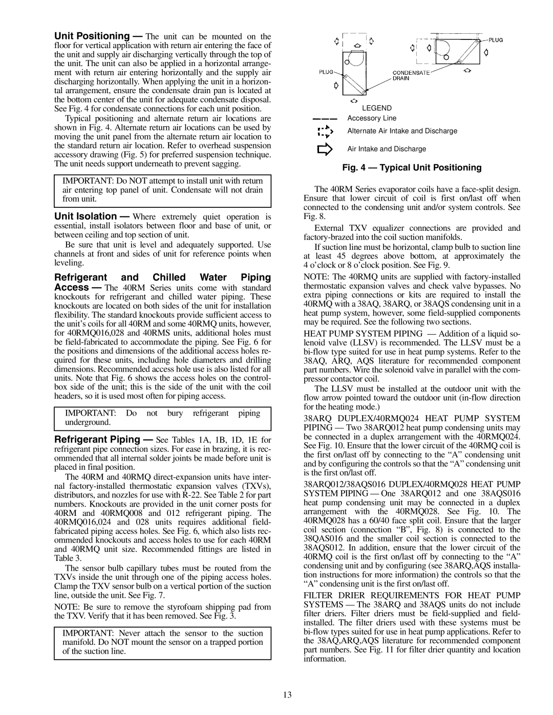
Unit Positioning — The unit can be mounted on the floor for vertical application with return air entering the face of the unit and supply air discharging vertically through the top of the unit. The unit can also be applied in a horizontal arrange- ment with return air entering horizontally and the supply air discharging horizontally. When applying the unit in a horizon- tal arrangement, ensure the condensate drain pan is located at the bottom center of the unit for adequate condensate disposal. See Fig. 4 for condensate connections for each unit position.
Typical positioning and alternate return air locations are shown in Fig. 4. Alternate return air locations can be used by moving the unit panel from the alternate return air location to the standard return air location. Refer to overhead suspension accessory drawing (Fig. 5) for preferred suspension technique. The unit needs support underneath to prevent sagging.
IMPORTANT: Do NOT attempt to install unit with return air entering top panel of unit. Condensate will not drain from unit.
Unit Isolation — Where extremely quiet operation is essential, install isolators between floor and base of unit, or between ceiling and top section of unit.
Be sure that unit is level and adequately supported. Use channels at front and sides of unit for reference points when leveling.
Refrigerant and Chilled Water Piping Access — The 40RM Series units come with standard knockouts for refrigerant and chilled water piping. These knockouts are located on both sides of the unit for installation flexibility. The standard knockouts provide sufficient access to the unit’s coils for all 40RM and some 40RMQ units, however, for 40RMQ016,028 and 40RMS units, additional holes must be
IMPORTANT: Do not bury refrigerant piping underground.
Refrigerant Piping — See Tables 1A, 1B, 1D, 1E for refrigerant pipe connection sizes. For ease in brazing, it is rec- ommended that all internal solder joints be made before unit is placed in final position.
The 40RM and 40RMQ
The sensor bulb capillary tubes must be routed from the TXVs inside the unit through one of the piping access holes. Clamp the TXV sensor bulb on a vertical portion of the suction line, outside the unit. See Fig. 7.
NOTE: Be sure to remove the styrofoam shipping pad from the TXV. Verify that it has been removed. See Fig. 3.
IMPORTANT: Never attach the sensor to the suction manifold. Do NOT mount the sensor on a trapped portion of the suction line.
LEGEND
Accessory Line
Alternate Air Intake and Discharge
Air Intake and Discharge
Fig. 4 — Typical Unit Positioning
The 40RM Series evaporator coils have a
External TXV equalizer connections are provided and
If suction line must be horizontal, clamp bulb to suction line at least 45 degrees above bottom, at approximately the 4 o’clock or 8 o’clock position. See Fig. 9.
NOTE: The 40RMQ units are supplied with
HEAT PUMP SYSTEM PIPING — Addition of a liquid so- lenoid valve (LLSV) is recommended. The LLSV must be a
The LLSV must be installed at the outdoor unit with the flow arrow pointed toward the outdoor unit
38ARQ DUPLEX/40RMQ024 HEAT PUMP SYSTEM PIPING — Two 38ARQ012 heat pump condensing units may be connected in a duplex arrangement with the 40RMQ024. See Fig. 10. Ensure that the lower circuit of the 40RMQ coil is the first on/last off by connecting to the “A” condensing unit and by configuring the controls so that the “A” condensing unit is the first on/last off.
38ARQ012/38AQS016 DUPLEX/40RMQ028 HEAT PUMP SYSTEM PIPING — One 38ARQ012 and one 38AQS016 heat pump condensing unit may be connected in a duplex arrangement with the 40RMQ028. See Fig. 10. The 40RMQ028 has a 60/40 face split coil. Ensure that the larger coil section (connection “B”, Fig. 8) is connected to the 38QAS016 and the smaller coil section is connected to the 38AQS012. In addition, ensure that the lower circuit of the 40RMQ coil is the first on/last off by connecting to the “A” condensing unit and by configuring (see 38ARQ,AQS installa- tion instructions for more information) the controls so that the “A” condensing unit is the first on/last off.
FILTER DRIER REQUIREMENTS FOR HEAT PUMP SYSTEMS — The 38ARQ and 38AQS units do not include filter driers. Filter driers must be
13