Centering Fan Wheel — If fan and fan shaft assembly are not properly centered, blades may scrape against scroll or may create an objectionable whistling noise. It may be neces- sary to adjust individual fan wheels or move entire fan shaft. See the following two sections.
Fan Shaft Position Adjustment — Loosen set- screw or locking collar of each fan shaft bearing. Slide shaft into correct position and replace locking collar (Fig. 21). To re- place locking collar, push collar up against inner face of bear- ing. Turn collar in direction of fan rotation until tight, and tight- en setscrew. Tightening locking collar in direction of fan rota- tion results in further tightening of collar should setscrew work itself loose.
Fig. 21 — Fan Shaft Bearing
Individual Fan Wheel Adjustment — Loosen the 2 locking bolts holding fan wheel hub to shaft. See Fig. 20. Position fan wheel in center of the fan housing and tighten locking bolts. Clearance between wheel and housing should be the same on both sides.
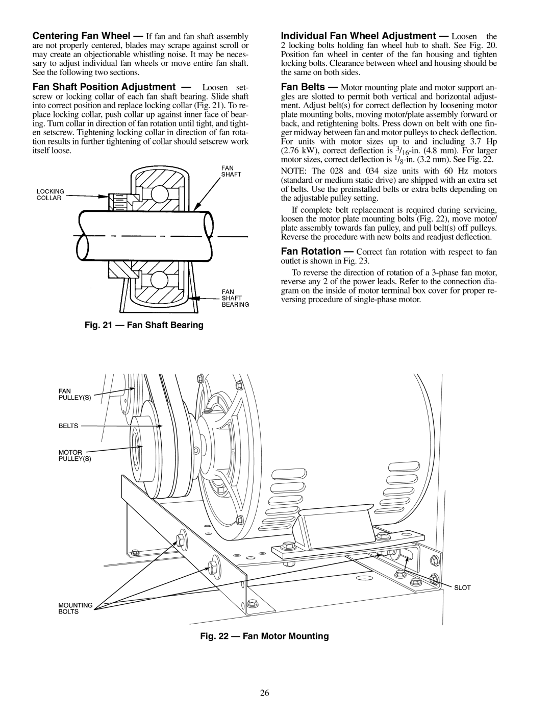
Fan Belts — Motor mounting plate and motor support an- gles are slotted to permit both vertical and horizontal adjust- ment. Adjust belt(s) for correct deflection by loosening motor plate mounting bolts, moving motor/plate assembly forward or back, and retightening bolts. Press down on belt with one fin- ger midway between fan and motor pulleys to check deflection. For units with motor sizes up to and including 3.7 Hp (2.76 kW), correct deflection is
NOTE: The 028 and 034 size units with 60 Hz motors (standard or medium static drive) are shipped with an extra set of belts. Use the preinstalled belts or extra belts depending on the adjustable pulley setting.
If complete belt replacement is required during servicing, loosen the motor plate mounting bolts (Fig. 22), move motor/ plate assembly towards fan pulley, and pull belt(s) off pulleys. Reverse the procedure with new bolts and readjust deflection.
Fan Rotation — Correct fan rotation with respect to fan outlet is shown in Fig. 23.
To reverse the direction of rotation of a
Fig. 22 — Fan Motor Mounting
26