Server Blades | Installation Sequence |
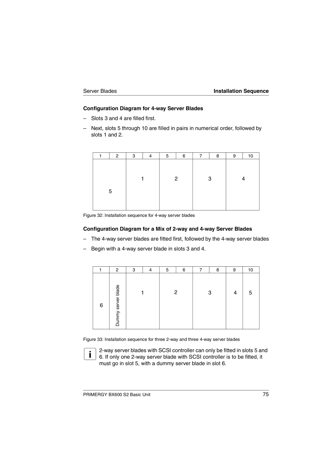
Configuration Diagram for 4-way Server Blades
–Slots 3 and 4 are filled first.
–Next, slots 5 through 10 are filled in pairs in numerical order, followed by slots 1 and 2.
1
2
3
4
5
6
7
8
9
10
1
2
3
4
5
Figure 32: Installation sequence for 4-way server blades
Configuration Diagram for a Mix of
–The
–Begin with a
1 | 2 | 3 |
| 4 | 5 |
| 6 | 7 |
| 8 | 9 | 10 |
| blade |
| 1 |
| 2 | 3 |
| 4 | 5 | |||
6 | Dummy server |
|
|
|
|
|
|
|
|
|
|
|
|
|
|
|
|
|
|
|
|
|
|
| |
|
|
|
|
|
|
|
|
|
|
|
|
|
Figure 33: Installation sequence for three 2-way and three 4-way server blades
I
PRIMERGY BX600 S2 Basic Unit | 75 |