Connecting External Devices |
|
|
| Installing the Hardware | ||||||||||
|
|
|
|
|
|
|
|
|
|
|
|
|
|
|
|
|
|
|
|
|
|
|
|
|
|
|
|
|
|
|
|
|
|
|
|
|
|
|
|
|
|
|
|
|
|
|
|
|
|
|
|
|
|
|
|
|
|
|
|
|
|
|
|
|
|
|
|
|
|
|
|
|
|
|
|
|
|
|
|
|
|
|
|
|
|
|
|
|
|
|
|
|
|
|
|
|
|
|
|
|
|
|
|
|
|
|
|
|
|
|
|
|
|
|
|
|
|
|
|
|
|
|
|
|
|
|
|
|
|
|
|
|
|
|
|
|
|
|
|
|
|
|
|
|
|
|
|
|
|
|
|
|
|
|
|
|
|
|
|
|
|
|
|
|
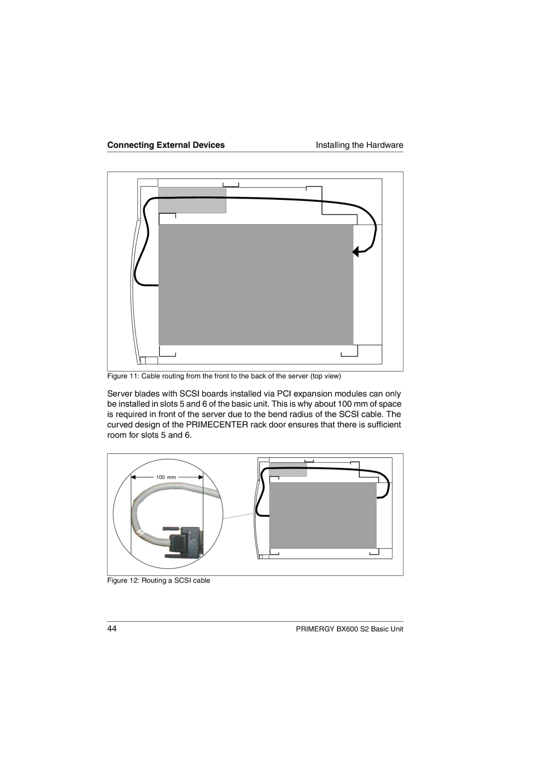
Figure 11: Cable routing from the front to the back of the server (top view)
Server blades with SCSI boards installed via PCI expansion modules can only be installed in slots 5 and 6 of the basic unit. This is why about 100 mm of space is required in front of the server due to the bend radius of the SCSI cable. The curved design of the PRIMECENTER rack door ensures that there is sufficient room for slots 5 and 6.
![]() 100mm
100mm ![]()
Figure 12: Routing a SCSI cable
44 | PRIMERGY BX600 S2 Basic Unit |
