FC Switch Blade | FC switch blade installation |
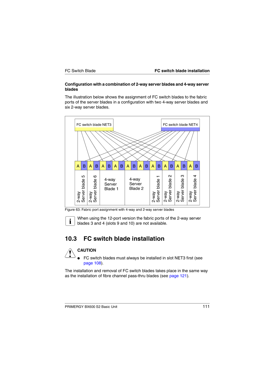
Configuration with a combination of
The illustration below shows the assignment of FC switch blades to the fabric ports of the server blades in a configuration with two
FC switch blade NET3 | FC switch blade NET4 |
|
|
A B A B A B A B A B A B A B A B A B A B |
5 | 6 | 1 | 2 | 3 | 4 | |||
blade | blade | blade | blade | blade | blade | |||
Server | Server | |||||||
|
|
|
|
|
| |||
Blade 1 | Blade 2 | |||||||
|
|
Figure 63: Fabric port assignment with 4-way and 2-way server blades
IWhen using the
10.3FC switch blade installation
VCAUTION
●FC switch blades must always be installed in slot NET3 first (see page 108).
The installation and removal of FC switch blades takes place in the same way as the installation of fibre channel
PRIMERGY BX600 S2 Basic Unit | 111 |
