Connecting External Devices | Installing the Hardware |
Connectors on the back of the basic unit
1
2
3
4
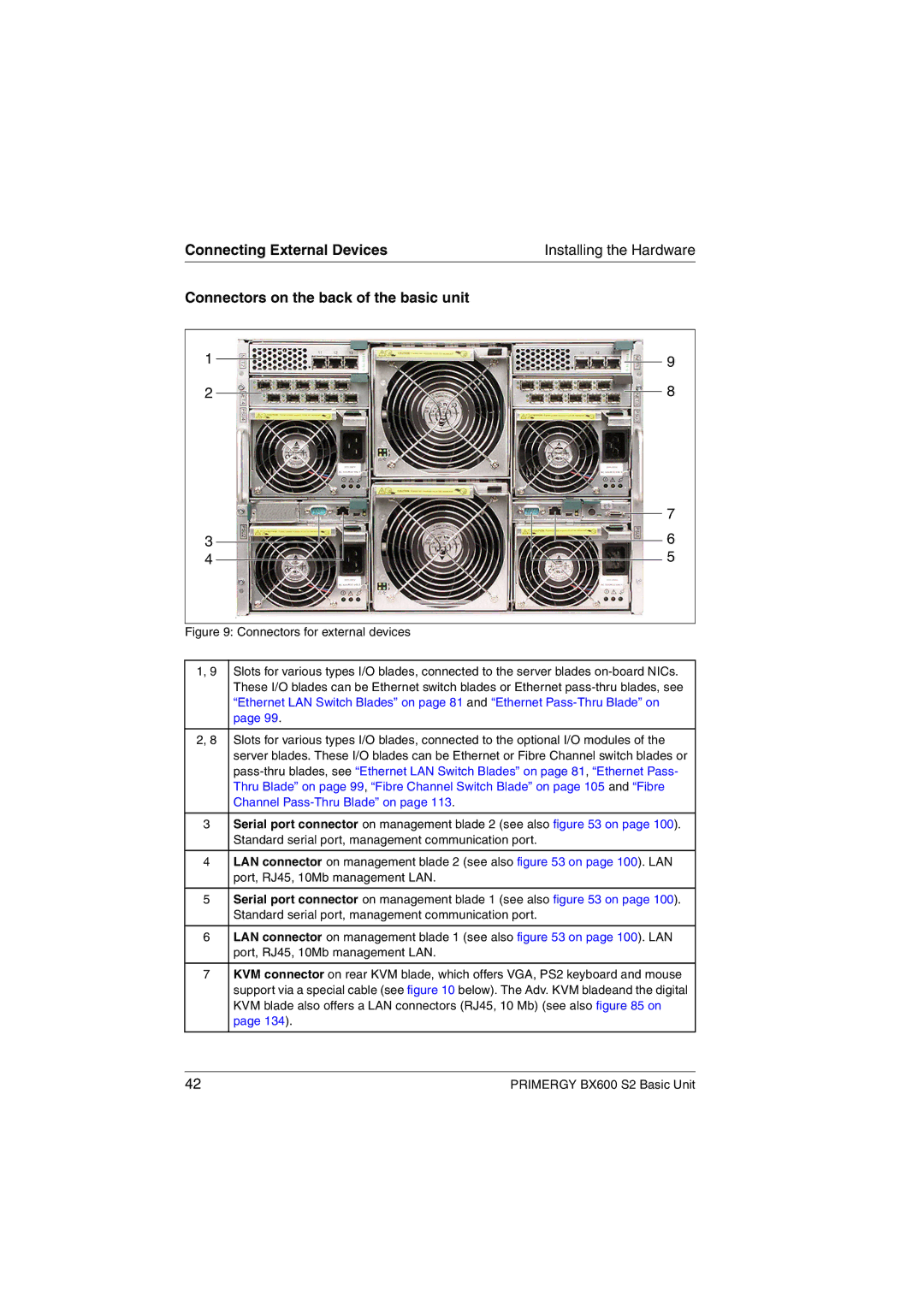
Figure 9: Connectors for external devices
9
8
7
6
5
1, 9 | Slots for various types I/O blades, connected to the server blades |
| These I/O blades can be Ethernet switch blades or Ethernet |
| “Ethernet LAN Switch Blades” on page 81 and “Ethernet |
| page 99. |
|
|
2, 8 | Slots for various types I/O blades, connected to the optional I/O modules of the |
| server blades. These I/O blades can be Ethernet or Fibre Channel switch blades or |
| |
| Thru Blade” on page 99, “Fibre Channel Switch Blade” on page 105 and “Fibre |
| Channel |
3Serial port connector on management blade 2 (see also figure 53 on page 100). Standard serial port, management communication port.
4LAN connector on management blade 2 (see also figure 53 on page 100). LAN port, RJ45, 10Mb management LAN.
5Serial port connector on management blade 1 (see also figure 53 on page 100). Standard serial port, management communication port.
6LAN connector on management blade 1 (see also figure 53 on page 100). LAN port, RJ45, 10Mb management LAN.
7KVM connector on rear KVM blade, which offers VGA, PS2 keyboard and mouse support via a special cable (see figure 10 below). The Adv. KVM bladeand the digital KVM blade also offers a LAN connectors (RJ45, 10 Mb) (see also figure 85 on page 134).
42 | PRIMERGY BX600 S2 Basic Unit |