Control and Connection Panel | FC Switch Blade |
10.1Control and Connection Panel
3 | 4 | 5 | 6 | 7 |
| 8 | 9 |
|
|
|
|
|
| 10 | 11 | 12 | 13 | 14 | 15 |
|
| ! |
|
|
|
|
|
|
|
|
|
|
| 2 |
|
| 1 |
|
|
|
|
|
|
|
|
|
|
|
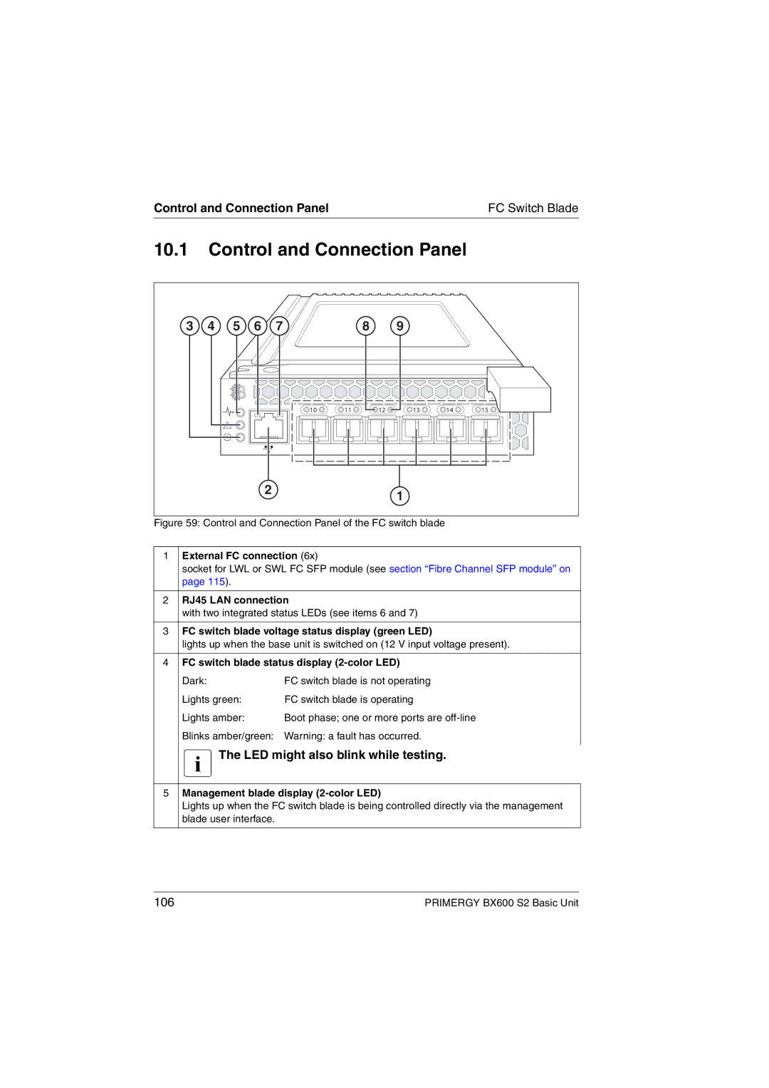
Figure 59: Control and Connection Panel of the FC switch blade
1 | External FC connection (6x) | |
| socket for LWL or SWL FC SFP module (see section “Fibre Channel SFP module” on | |
| page 115). |
|
|
| |
2 | RJ45 LAN connection | |
| with two integrated status LEDs (see items 6 and 7) | |
|
| |
3 | FC switch blade voltage status display (green LED) | |
| lights up when the base unit is switched on (12 V input voltage present). | |
|
| |
4 | FC switch blade status display | |
| Dark: | FC switch blade is not operating |
| Lights green: | FC switch blade is operating |
| Lights amber: | Boot phase; one or more ports are |
| Blinks amber/green: Warning: a fault has occurred. | |
| IThe LED might also blink while testing. | |
5Management blade display (2-color LED)
Lights up when the FC switch blade is being controlled directly via the management blade user interface.
106 | PRIMERGY BX600 S2 Basic Unit |