Control and Connection Panel | Management Blade |
12.1Control and Connection Panel
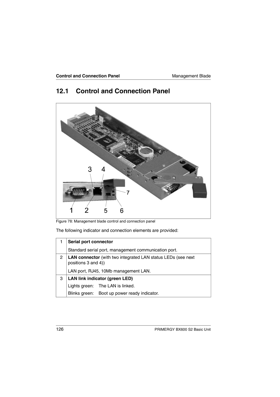
Figure 78: Management blade control and connection panel
The following indicator and connection elements are provided:
1Serial port connector
Standard serial port, management communication port.
2LAN connector (with two integrated LAN status LEDs (see next positions 3 and 4))
LAN port, RJ45, 10Mb management LAN.
3LAN link indicator (green LED) Lights green: The LAN is linked.
Blinks green: Boot up power ready indicator.
126 | PRIMERGY BX600 S2 Basic Unit |