Table 6 — Fan Contactor Coil Data
| UNIT | VOLTAGE | MAXIMUM |
| 40RM, 40RMQ | HOLDING |
| (vac) |
| 40RMS | VA |
| |
| 007-034 | 24 | 10 |
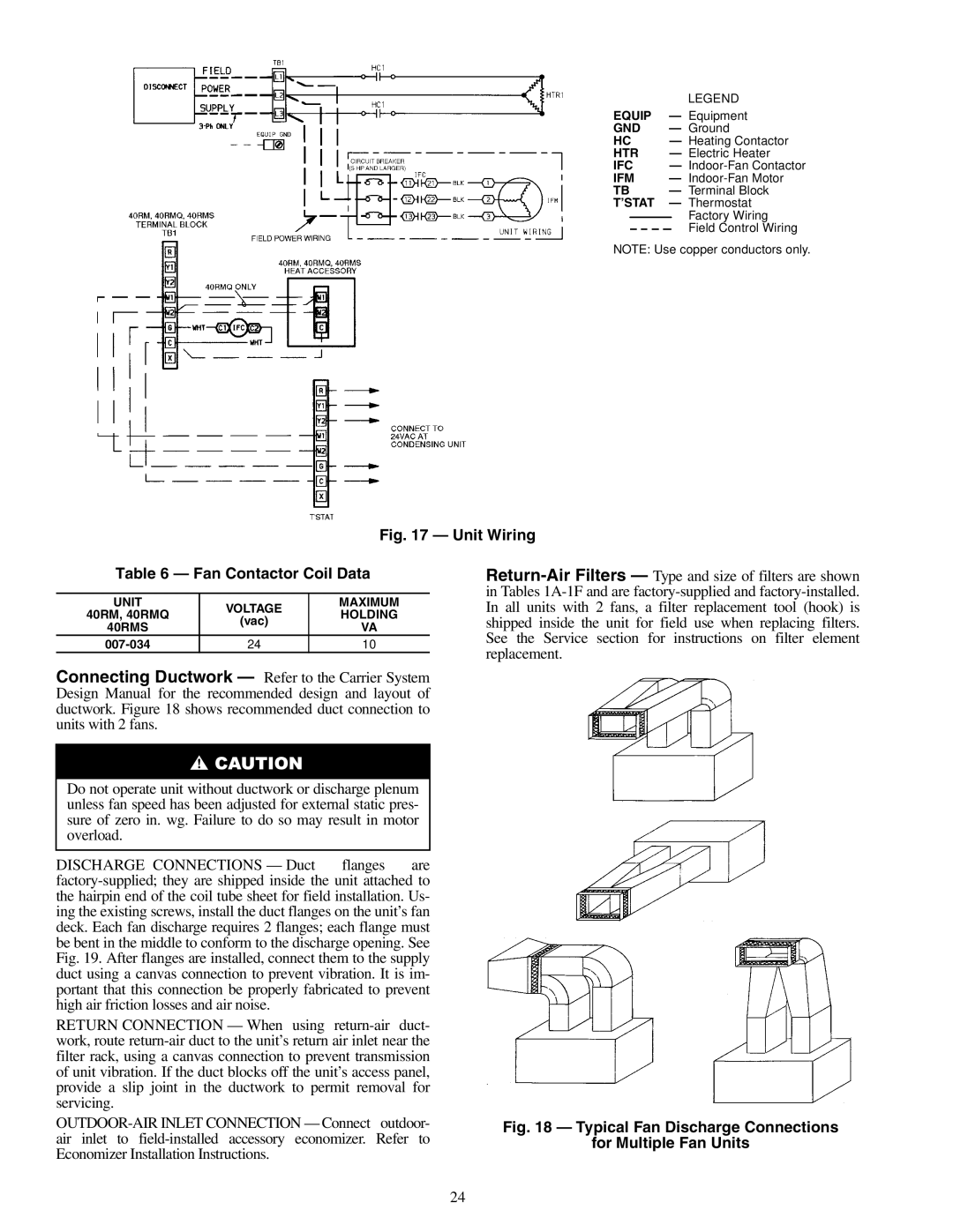
Connecting Ductwork — Refer to the Carrier System Design Manual for the recommended design and layout of ductwork. Figure 18 shows recommended duct connection to units with 2 fans.
Do not operate unit without ductwork or discharge plenum unless fan speed has been adjusted for external static pres- sure of zero in. wg. Failure to do so may result in motor overload.
DISCHARGE CONNECTIONS — Duct flanges are factory-supplied; they are shipped inside the unit attached to the hairpin end of the coil tube sheet for field installation. Us- ing the existing screws, install the duct flanges on the unit’s fan deck. Each fan discharge requires 2 flanges; each flange must be bent in the middle to conform to the discharge opening. See Fig. 19. After flanges are installed, connect them to the supply duct using a canvas connection to prevent vibration. It is im- portant that this connection be properly fabricated to prevent high air friction losses and air noise.
RETURN CONNECTION — When using return-air duct- work, route return-air duct to the unit’s return air inlet near the filter rack, using a canvas connection to prevent transmission of unit vibration. If the duct blocks off the unit’s access panel, provide a slip joint in the ductwork to permit removal for servicing.
OUTDOOR-AIR INLET CONNECTION — Connect outdoor- air inlet to field-installed accessory economizer. Refer to Economizer Installation Instructions.
Return-Air Filters — Type and size of filters are shown in Tables 1A-1F and are factory-supplied and factory-installed. In all units with 2 fans, a filter replacement tool (hook) is shipped inside the unit for field use when replacing filters. See the Service section for instructions on filter element replacement.
Fig. 18 — Typical Fan Discharge Connections
for Multiple Fan Units