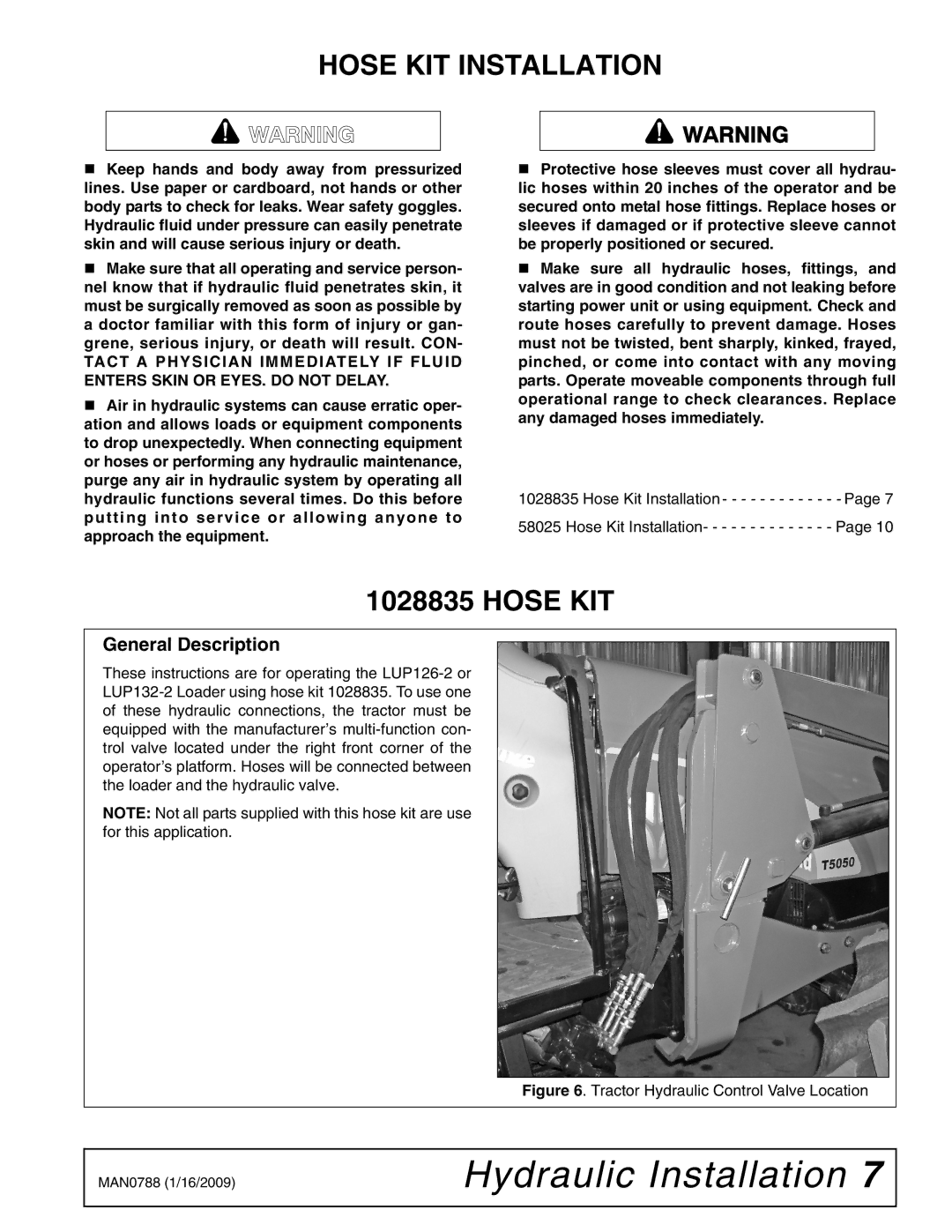
T5050, T5040, T5060, T5070 specifications
Woods Equipment is renowned for its commitment to quality and innovation in the agricultural sector, and its T-series of tractors, specifically the T5060, T5040, T5070, and T5050 models, exemplify this dedication. Each model in the T-series is designed to cater to the diverse needs of modern farmers by offering robust capabilities, user-friendly features, and advanced technology to enhance productivity and efficiency.The T5060 model stands out with its powerful engine that delivers exceptional torque and horsepower, making it ideal for varied field tasks. It features a spacious cab designed for operator comfort, equipped with ergonomic controls that ensure ease of use during long hours in the field. The T5060 also incorporates advanced hydraulic systems that allow for quick attachment and detachment of implements, making it a versatile choice for any farming operation.
Similarly, the T5040 model is engineered for reliability and efficiency. This tractor offers a balance of power and fuel economy, which is critical for cost-control in farming operations. The T5040 comes with a robust transmission system that ensures smooth shifting and optimal power delivery, while its heavy-duty chassis provides stability and durability in challenging agricultural environments.
The T5070 model takes performance to the next level with its enhanced engine technology that meets modern emission standards, providing cleaner operation without sacrificing power. This model is particularly noted for its excellent traction and maneuverability, making it suitable for both large-scale and intricate farming tasks. Operators will also appreciate the advanced digital display that monitors essential performance metrics, allowing for informed decision-making in real-time.
Finally, the T5050 model combines cutting-edge technology with easy-to-use features. It is equipped with integrated GPS systems that assist in precision farming, streamlining field operations and improving crop management. The T5050 also features a premium cab with climate control, ensuring that operators remain comfortable regardless of the weather conditions.
In summary, the Woods Equipment T-series tractors—the T5060, T5040, T5070, and T5050—offer powerful performance, advanced technology, and user-centric design. Each model supports farmers in maximizing productivity while enhancing comfort and efficiency on the field. Whether for heavy-duty tasks or precision farming, these tractors represent Woods Equipment's commitment to facilitating agricultural success.

