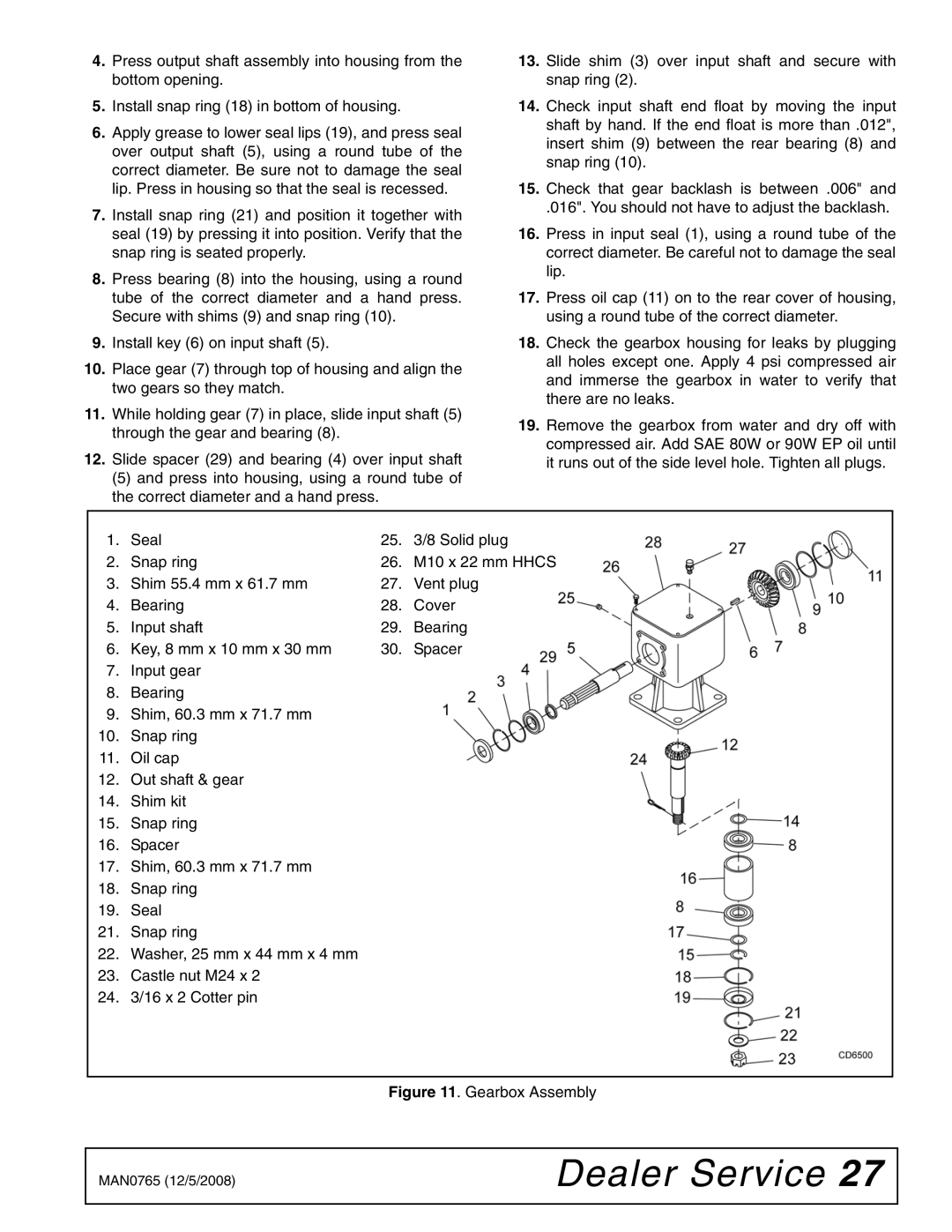
4.Press output shaft assembly into housing from the bottom opening.
5.Install snap ring (18) in bottom of housing.
6.Apply grease to lower seal lips (19), and press seal over output shaft (5), using a round tube of the correct diameter. Be sure not to damage the seal lip. Press in housing so that the seal is recessed.
7.Install snap ring (21) and position it together with seal (19) by pressing it into position. Verify that the snap ring is seated properly.
8.Press bearing (8) into the housing, using a round tube of the correct diameter and a hand press. Secure with shims (9) and snap ring (10).
9.Install key (6) on input shaft (5).
10.Place gear (7) through top of housing and align the two gears so they match.
11.While holding gear (7) in place, slide input shaft (5) through the gear and bearing (8).
12.Slide spacer (29) and bearing (4) over input shaft
(5) and press into housing, using a round tube of the correct diameter and a hand press.
13.Slide shim (3) over input shaft and secure with snap ring (2).
14.Check input shaft end float by moving the input shaft by hand. If the end float is more than .012", insert shim (9) between the rear bearing (8) and snap ring (10).
15.Check that gear backlash is between .006" and
.016". You should not have to adjust the backlash.
16.Press in input seal (1), using a round tube of the correct diameter. Be careful not to damage the seal lip.
17.Press oil cap (11) on to the rear cover of housing, using a round tube of the correct diameter.
18.Check the gearbox housing for leaks by plugging all holes except one. Apply 4 psi compressed air and immerse the gearbox in water to verify that there are no leaks.
19.Remove the gearbox from water and dry off with compressed air. Add SAE 80W or 90W EP oil until it runs out of the side level hole. Tighten all plugs.
1. | Seal | 25. | 3/8 Solid plug |
2. | Snap ring | 26. | M10 x 22 mm HHCS |
3. | Shim 55.4 mm x 61.7 mm | 27. | Vent plug |
4. | Bearing | 28. | Cover |
5. | Input shaft | 29. | Bearing |
6. | Key, 8 mm x 10 mm x 30 mm | 30. | Spacer |
7.Input gear
8.Bearing
9.Shim, 60.3 mm x 71.7 mm
10.Snap ring
11.Oil cap
12.Out shaft & gear
14.Shim kit
15.Snap ring
16.Spacer
17.Shim, 60.3 mm x 71.7 mm
18.Snap ring
19.Seal
21.Snap ring
22.Washer, 25 mm x 44 mm x 4 mm
23.Castle nut M24 x 2
24.3/16 x 2 Cotter pin
Figure 11. Gearbox Assembly
MAN0765 (12/5/2008) | Dealer Service 27 |
|
|