Construction and Assembly
Once you have determined the material you will use and the size and shape of your clamp jaws, you are ready to begin construction and assembly.
To construct and assemble the clamps, do these steps:
1.Use the drawing and dimensions from Figure 2 or your own design to cut out the shape of the clamp jaws. Sand all edges to reduce splinters and workpiece marring.
Drill Holes for |
Threaded Rods |
(Aligned with |
Dowel Nut Holes) |
(x2) |
Note: The following illustrations show a standard jaw shape. The jaws you create for your clamp can be customized as desired.
2.Drill four holes for the dowel pins in the locations shown in Figure 2 or the approximate locations shown in Figure 3. Refer to Sizing Information on the Page 2 for the proper hole size.
Drill Holes for |
Dowel Nuts |
(x2) |
Figure 3. Drilling dowel nut holes.
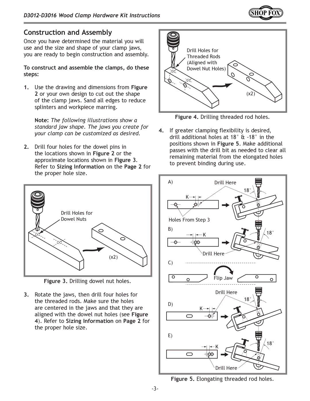
3.Rotate the jaws, then drill four holes for the threaded rods. Make sure the holes are centered in the jaws and that they are aligned with the dowel nut holes (see Figure 4). Refer to Sizing Information on Page 2 for the proper hole size.
Figure 4. Drilling threaded rod holes.
4.If greater clamping flexibility is desired, drill additional holes at 18° & -18° in the positions shown in Figure 5. Make additional passes with the drill bit as needed to clear all remaining material from the elongated holes to prevent binding during use.
A) | Drill Here |
|
|
| 18° |
| K |
|
Holes From Step 3 |
| |
B) | K | 18° |
| ||
|
| |
| Drill Here |
|
C) |
|
|
| Flip Jaw |
|
| Drill Here |
|
D) |
| 18° |
K |
| |
|
| |
E) |
|
|
| K | 18° |
|
| |
| Drill Here |
|