D4041 Miter Saw Stand Instructions
Inventory
In the event that any nonproprietary parts are missing (e.g. a nut or a washer), we would be glad to replace them, or for the sake of expediency, replacements can be obtained at your local hardware store.
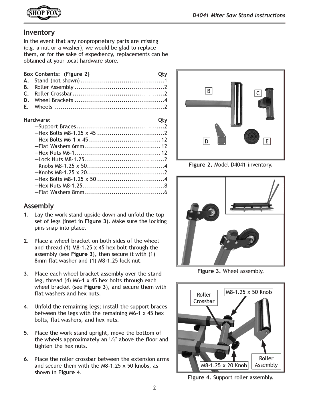
Box Contents: (Figure 2) | Qty | |
A. | Stand (not shown) | 1 |
B. | Roller Assembly | 2 |
C. | Roller Crossbar | 2 |
D. | Wheel Brackets | 4 |
E. | Wheels | 2 |
|
|
|
Hardware: | Qty | |
| 2 | |
| 2 | |
| 12 | |
| 12 | |
| 12 | |
| 2 | |
| 4 | |
| 2 | |
| 4 | |
| 8 | |
| 6 | |
Assembly
1.Lay the work stand upside down and unfold the top set of legs (inset in Figure 3). Make sure the locking pins snap into place.
2.Place a wheel bracket on both sides of the wheel and thread (1)
8mm flat washer and (1)
3.Place each wheel bracket assembly over the stand leg, thread (4)
4.Unfold the remaining legs; install the support braces between the legs with the remaining
5.Place the work stand upright, move the bottom of the wheels approximately an 1⁄8" above the floor and tighten the hex nuts.
6.Place the roller crossbar between the extension arms and secure them with the
BC
D |
| E |
Figure 2. Model D4041 inventory.
Figure 3. Wheel assembly.
Roller |
| |
|
| |
Crossbar |
|
|
|
| Roller |
Assembly | ||