W1758 Owner's Manual (Mfg. Since 3/10)
3.Using the 6mm hex wrench, secure the lathe to the legs with the eight cap screws and lock washers, as shown in Figure 8.
4.Install the handle into the tool rest, as shown in
Figure 9.
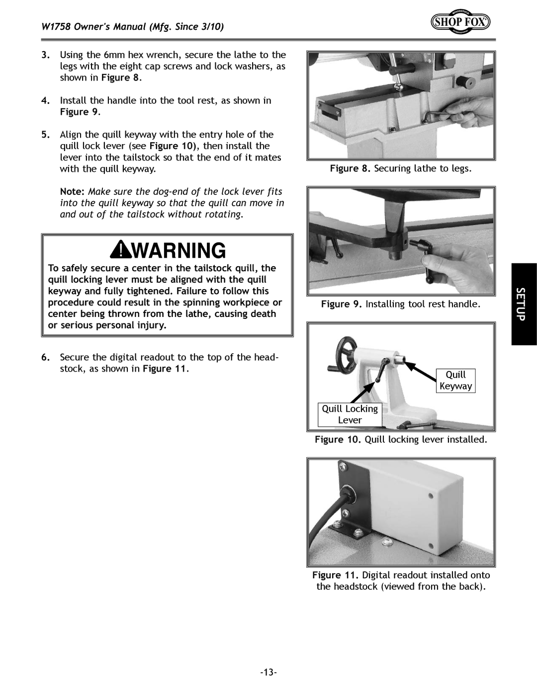
5.Align the quill keyway with the entry hole of the quill lock lever (see Figure 10), then install the lever into the tailstock so that the end of it mates with the quill keyway.
Note: Make sure the
To safely secure a center in the tailstock quill, the quill locking lever must be aligned with the quill keyway and fully tightened. Failure to follow this procedure could result in the spinning workpiece or center being thrown from the lathe, causing death or serious personal injury.
6.Secure the digital readout to the top of the head- stock, as shown in Figure 11.
Figure 8. Securing lathe to legs.
Figure 9. Installing tool rest handle.
Quill
Keyway
Quill Locking
Lever
SETUP