Page 2 | Model MRC44CB1 |
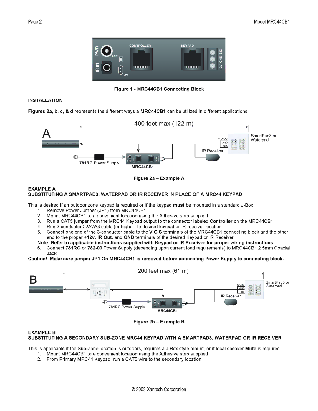
PWR | LED1 |
| |
IR IN |
|
CONTROLLER
JP1
KEYPAD
![]()
![]()
![]()
![]()
![]() +12V GND SIG
+12V GND SIG
Figure 1 - MRC44CB1 Connecting Block
INSTALLATION
Figures 2a, b, c, & d represents the different ways a MRC44CB1 can be utilized in different applications.
A
400 feet max (122 m)
+12VDC
GND
SIG
IR Receiver
| PWR | CONTROLLER | KEYPAD |
| LED1 | SIG | |
781RG Power Supply | IR IN |
| +12V GND |
| JP1 |
|
MRC44CB1
SmartPad3 or Waterpad
Figure 2a – Example A
EXAMPLE A
SUBSTITUTING A SMARTPAD3, WATERPAD OR IR RECEIVER IN PLACE OF A MRC44 KEYPAD
This is desired if an outdoor zone keypad is required or if the keypad must be mounted in a standard
1.Remove Power Jumper (JP1) from MRC44CB1
2.Mount MRC44CB1 to a convenient location using the Adhesive strip supplied
3.Run a CAT5 jumper from the MRC44 Keypad output to the connector labeled Controller on the MRC44CB1
4.Run 3 conductor 22AWG cable (or higher) to desired keypad or IR receiver location
5.Connect one end of the
Note: Refer to applicable instructions supplied with Keypad or IR Receiver for proper wiring instructions.
6.Connect 781RG or
Caution! Make sure jumper JP1 On MRC44CB1 is removed before connecting Power Supply to connecting block.
B
200 feet max (61 m)
SmartPad3 or
+12VDCWaterpad
GND
SIG
IR Receiver
| PWR | CONTROLLER | KEYPAD |
| LED1 | SIG | |
781RG Power Supply | IR IN |
| +12V GND |
| JP1 |
|
MRC44CB1
Figure 2b – Example B
EXAMPLE B
SUBSTITUTING A SECONDARY
1.Mount MRC44CB1 to a convenient location using the Adhesive strip supplied
2.From Primary MRC44 Keypad, run a CAT5 wire to the secondary location.
© 2002 Xantech Corporation