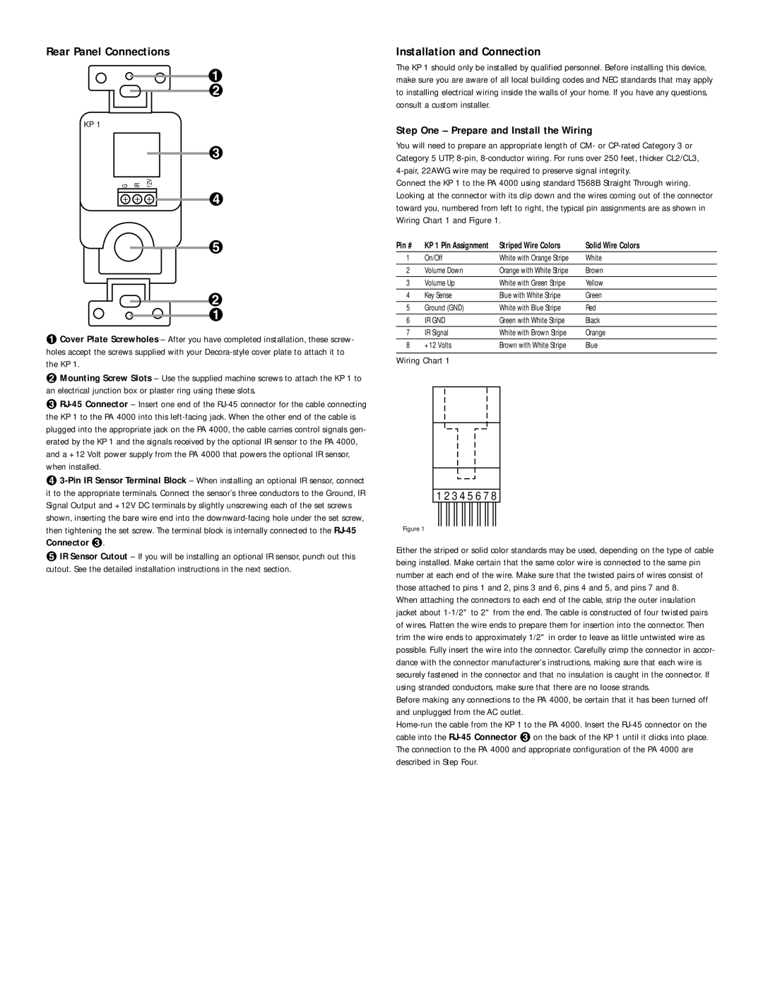
Rear Panel Connections
¡
™
KP 1
£
G | IR | 12V |
¢
∞
™
¡
¡Cover Plate Screwholes – After you have completed installation, these screw- holes accept the screws supplied with your
™ Mounting Screw Slots – Use the supplied machine screws to attach the KP 1 to an electrical junction box or plaster ring using these slots.
£
¢
∞ IR Sensor Cutout – If you will be installing an optional IR sensor, punch out this
cutout. See the detailed installation instructions in the next section.
Installation and Connection
The KP 1 should only be installed by qualified personnel. Before installing this device, make sure you are aware of all local building codes and NEC standards that may apply to installing electrical wiring inside the walls of your home. If you have any questions, consult a custom installer.
Step One – Prepare and Install the Wiring
You will need to prepare an appropriate length of CM- or
Connect the KP 1 to the PA 4000 using standard T568B Straight Through wiring. Looking at the connector with its clip down and the wires coming out of the connector toward you, numbered from left to right, the typical pin assignments are as shown in Wiring Chart 1 and Figure 1.
Pin # | KP 1 Pin Assignment | Striped Wire Colors | Solid Wire Colors |
1 | On/Off | White with Orange Stripe | White |
2 | Volume Down | Orange with White Stripe | Brown |
3 | Volume Up | White with Green Stripe | Yellow |
4 | Key Sense | Blue with White Stripe | Green |
5 | Ground (GND) | White with Blue Stripe | Red |
6 | IR GND | Green with White Stripe | Black |
7 | IR Signal | White with Brown Stripe | Orange |
8 | +12 Volts | Brown with White Stripe | Blue |
Wiring Chart 1
1 2 3 4 5 6 7 8
Figure 1
Either the striped or solid color standards may be used, depending on the type of cable being installed. Make certain that the same color wire is connected to the same pin number at each end of the wire. Make sure that the twisted pairs of wires consist of those attached to pins 1 and 2, pins 3 and 6, pins 4 and 5, and pins 7 and 8.
When attaching the connectors to each end of the cable, strip the outer insulation jacket about
Before making any connections to the PA 4000, be certain that it has been turned off and unplugged from the AC outlet.