INSTALLATION
•Bolt the positive (+) battery cable with 3/8'' ring terminal to the positive (red +) terminal assembly on the side of the inverter. Tighten the battery terminal bolts to a torque value between 160
The negative
The positive (+) battery cable must be fused and connected to the positive post of the house or auxiliary battery bank, or through a selector switch to one or more battery banks.
A spark may be generated when the final battery connection is made. This is normal; do not be alarmed. However, do not make the final connection in the presence of flammable fumes.
If multiple batteries are used, the interconnecting jumper cables should be the same AWG as those connected to the inverter/charger.
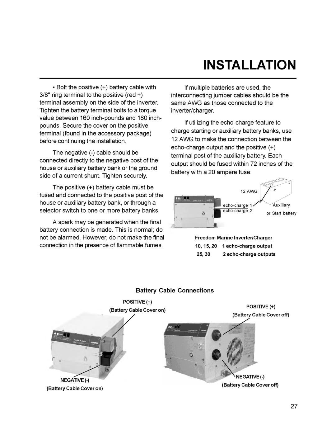
If utilizing the
12 AWG |
| |
1 | Auxiliary | |
2 | or Start battery | |
|
| |
Freedom Marine Inverter/Charger 10, 15, 20 1
25, 30 2
Battery Cable Connections
POSITIVE (+)
(Battery Cable Cover on)
POSITIVE (+)
(Battery Cable Cover off)
NEGATIVE
NEGATIVE
(Battery Cable Cover on)
(Battery Cable Cover off)
27