Features
DC Panel
WARNING: Shock,energy, and fire hazards. Readmanualbeforeinstallingor using.To preventfire, do not coveror obstructventilationopenings. Do not mount in
BATTERY
POS. 3
2 ![]()
DANGER: This unit employscompo- nents that tend to producearcs or sparks. Risk of fire and explosion– Do not install near batteries, in machinery space, or area in which
1![]()
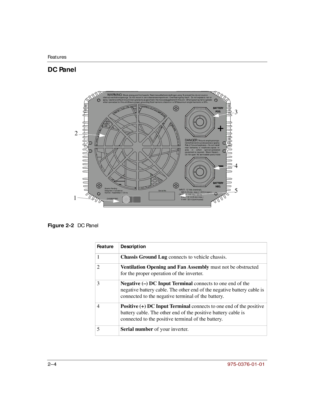
Figure 2-2 DC Panel
Patents Pending Designed in Canada by Xantrex / Assembled in China
CHASSIS GND
BATTERY
NEG.
Serial No. | INPUT: 12 Vdc (nominal), | |
520 A (5 min. max.) / 415 A (cont.) | ||
| OUTPUT: 120 Vac / 60 Hz | |
| 5 kW / 41 | A (5 min max.) |
| 4 kW / 33 | A (continuous) |
![]() 4
4
5
Feature | Description |
|
|
1 | Chassis Ground Lug connects to vehicle chassis. |
|
|
2 | Ventilation Opening and Fan Assembly must not be obstructed |
| for the proper operation of the inverter. |
|
|
3 | Negative |
| negative battery cable. The other end of the negative battery cable is |
| connected to the negative terminal of the battery. |
|
|
4 | Positive (+) DC Input Terminal connects to one end of the positive |
| battery cable. The other end of the positive battery cable is |
| connected to the positive terminal of the battery. |
|
|
5 | Serial number of your inverter. |
|
|