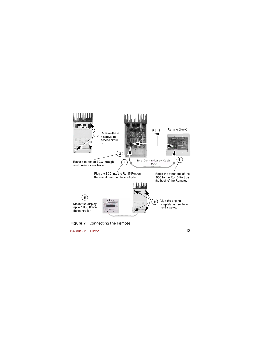
1 Remove these |
|
|
|
| Remote (back) | ||||
|
| Port |
|
|
|
| |||
4 screws to |
|
|
|
|
|
|
|
|
|
|
|
|
|
|
|
|
|
| |
access circuit |
|
|
|
|
|
|
|
|
|
board. |
|
|
|
|
|
|
|
|
|
|
|
|
|
|
|
|
|
| |
2 |
|
|
|
|
|
|
|
|
|
|
|
|
|
|
|
|
|
| |
|
|
|
|
|
|
|
|
| |
Route one end of SCC through | 3 | Serial Communications Cable | 4 | ||||||
| (SCC) |
|
|
|
| ||||
strain relief on controller. |
|
|
|
|
|
| |||
|
|
|
|
|
|
|
|
| |
Plug the SCC into the
5
Mount the display up to 1,000 ft from the controller.
Route the other end of the SCC to the
6Align the original faceplate and replace the 4 screws.
Figure 7 Connecting the Remote
13 |
