Front Panel (AC End)
Front Panel (AC End)
➃
| ON |
|
|
|
| OF F |
|
|
|
➆ |
|
|
|
|
➀ | ➁ | ➂ | ➅ | ➆ |
|
| ➄ |
|
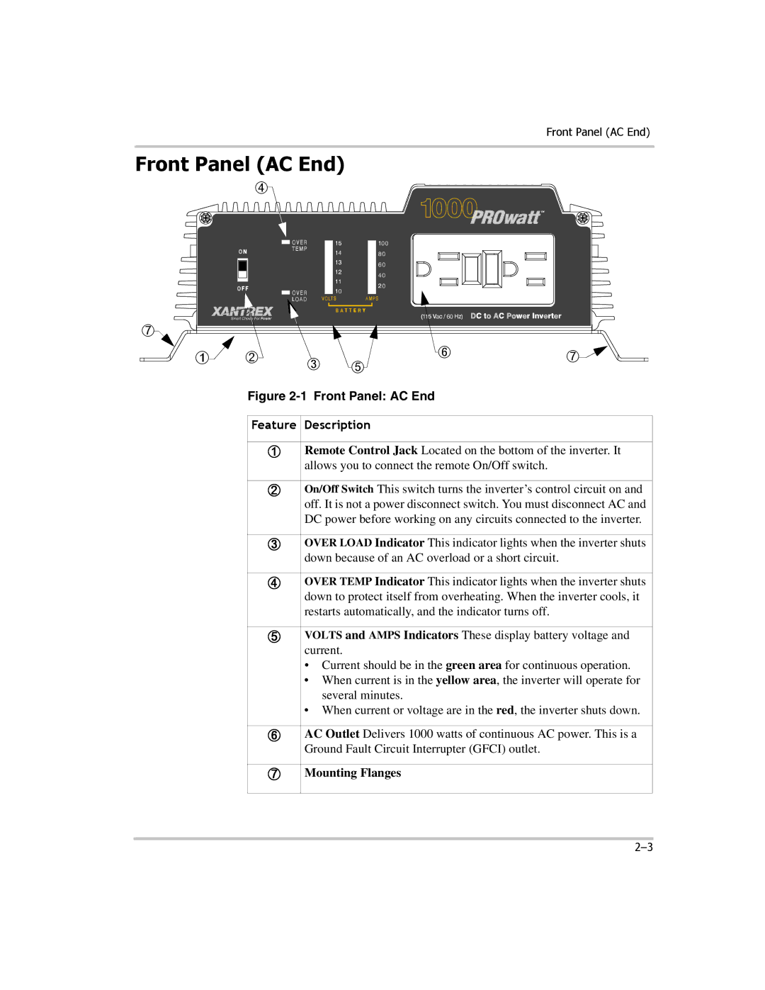
Figure 2-1 Front Panel: AC End
Feature | Description |
|
|
➀ | Remote Control Jack Located on the bottom of the inverter. It |
| allows you to connect the remote On/Off switch. |
|
|
➁ | On/Off Switch This switch turns the inverter’s control circuit on and |
| off. It is not a power disconnect switch. You must disconnect AC and |
| DC power before working on any circuits connected to the inverter. |
|
|
➂ | OVER LOAD Indicator This indicator lights when the inverter shuts |
| down because of an AC overload or a short circuit. |
|
|
➃ | OVER TEMP Indicator This indicator lights when the inverter shuts |
| down to protect itself from overheating. When the inverter cools, it |
| restarts automatically, and the indicator turns off. |
|
|
➄ | VOLTS and AMPS Indicators These display battery voltage and |
| current. |
| • Current should be in the green area for continuous operation. |
| • When current is in the yellow area, the inverter will operate for |
| several minutes. |
| • When current or voltage are in the red, the inverter shuts down. |
|
|
➅ | AC Outlet Delivers 1000 watts of continuous AC power. This is a |
| Ground Fault Circuit Interrupter (GFCI) outlet. |
|
|
➆ | Mounting Flanges |
|
|