RS232-XT, RS232-HPD specifications
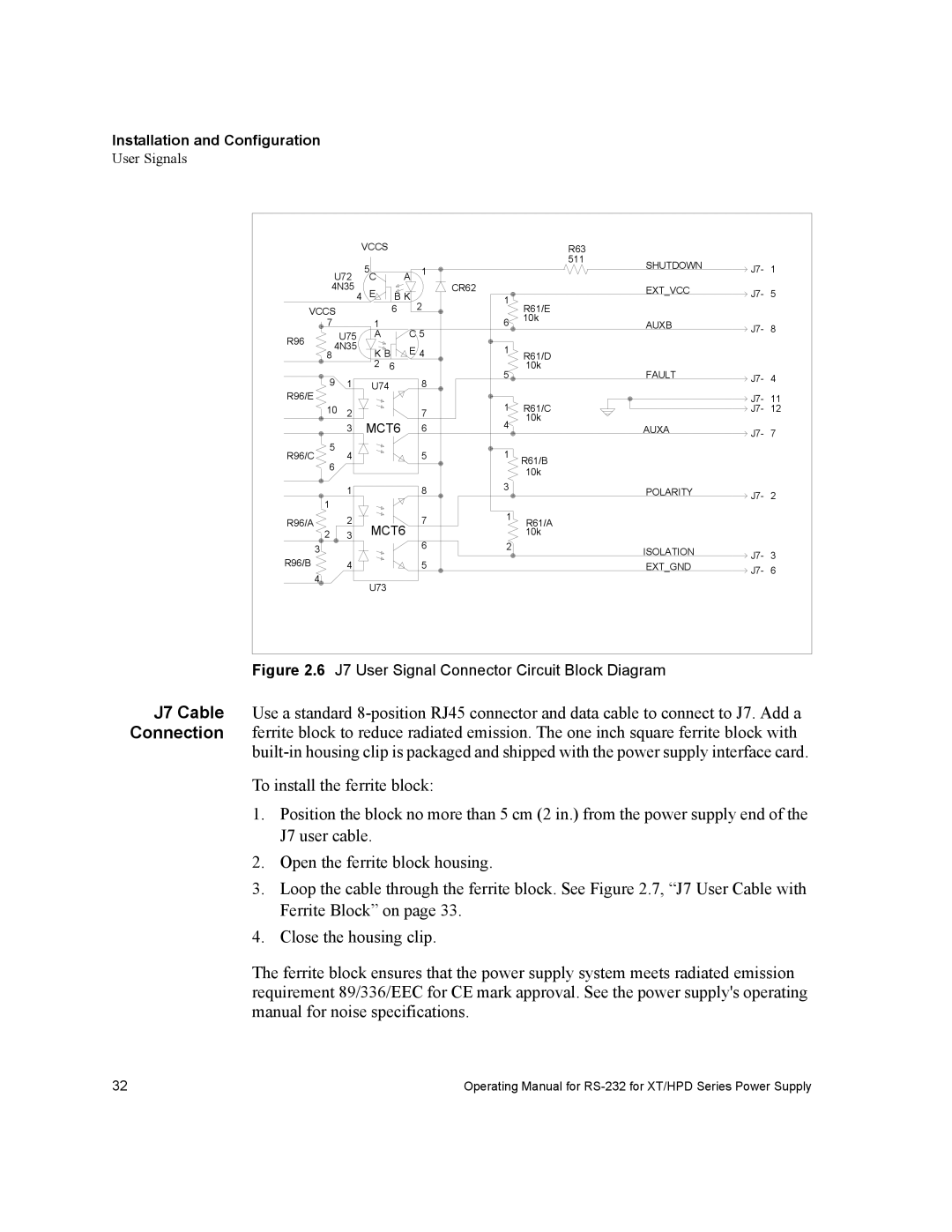
Xantrex Technology has made significant strides in the field of power electronics, particularly with its RS232-HPD and RS232-XT communication interfaces. These devices are designed to enhance the efficiency and reliability of power management systems, providing users with advanced features and robust technologies.The RS232-HPD (High Power Device) is optimized for high-performance applications, enabling seamless communication between power devices and control systems. One of its key features is its compatibility with a wide range of power inverters and converters, making it suitable for diverse applications including renewable energy systems, industrial automation, and marine power solutions. The RS232-HPD supports higher baud rates, allowing for faster data transmission and improved responsiveness in monitoring and control operations.
On the other hand, the RS232-XT (Extended Temperature) variant takes durability to the next level. It is designed to operate in extreme temperature conditions, which is crucial for applications located in harsh environments. The RS232-XT retains all the fundamental benefits of the RS232-HPD while providing additional resilience against temperature fluctuations. This feature is particularly advantageous for outdoor installations, where temperature extremes can impact performance and reliability.
Both the RS232-HPD and RS232-XT are equipped with extensive diagnostic tools that enable users to monitor system performance in real-time. These tools include error detection algorithms and status monitoring, which help in identifying potential issues before they escalate. The user-friendly interface simplifies the setup process, making it accessible for both experienced users and those new to power system management.
A standout characteristic of these interfaces is their robust communication protocols, designed to ensure secure data transmission. With built-in protection against common electrical anomalies, such as voltage spikes and electromagnetic interference, the Xantrex RS232 series guarantees uninterrupted operation and data integrity.
Integration with existing systems is straightforward, thanks to their standard RS232 connectivity. This compatibility makes them ideal for retrofitting older systems without the need for significant infrastructure changes.
In conclusion, Xantrex Technology's RS232-HPD and RS232-XT interfaces are exemplary solutions for advanced power management, offering high performance, durability, and ease of use. Their innovative features and robust technologies solidify Xantrex's position as a leader in the power electronics market. Whether for residential, commercial, or industrial applications, these devices stand ready to deliver efficient and reliable power management solutions.

