Xilinx Frequency Generator manual Direct Digital Synthesis DDS Circuit Diagram, ×16

Models: Frequency Generator

1 14
Download 14 pages 20.8 Kb
Page 7
Image 7

Direct Digital Synthesis (DDS) Circuit Diagram

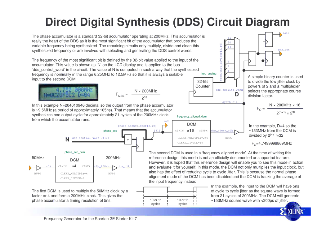
The phase accumulator is a standard 32-bit accumulator operating at 200MHz. This accumulator is


io12


31


really the heart of the DDS as it is the most significant bit of the accumulator that produces the


divider[31:0]

30


variable frequency being synthesized. The remaining circuits only multiply, divide and clean this


29


synthesized frequency or are involved with selecting and generating the DDS control words.


sma_out


The frequency of the most significant bit is defined by the 32-bit value applied to the input of the


3


accumulator. This value is shown as ‘N’ on the LCD display and is applied to the bus


frequency_

2


‘dds_control_word’ in the circuit. The value of N is computed in such a way that the synthesized

freq_scaling

1


frequency is nominally in the range 6.25MHz to 12.5MHz so that it is always a suitable


0

A simple binary counter is used


input to the second DCM.


32-Bit


to divide the low jitter clock by


Counter

dds_scaling_word

powers of 2 and a multiplexer


N × 200MHz


selects the appropriate course

FMSB =


D

232


division factor.


synth_clk


In this example N=204010946 decimal so the output from the phase accumulator


N × 200MHz × 16


FO =

is ~9.5MHz (a period of approximately 105ns). That means that the accumulator


2(D+1) × 232

synthesizes one output cycle for approximately 21 cycles of the 200MHz clock

frequency_aligned_dcm


from which the accumulator runs.


io9


DCM


phase_accumulator[31:0]


In the example, D=4 so the


×16


phase_acc


[31]


CLKIN

CLKFX

dcm_clean_clk

~153MHz from the DCM is

N dds_control_word[31:0]

+


CLKFX_MULTIPLY=256


BUFG

divided by 2(4+1)=32


FO=4.7499999869MHz


CLKFX_DIVIDE=16


phase_acc_dcm


The second DCM is used in a ‘frequency aligned mode’. At the time of writing this


50MHz


200MHz


reference design, this mode is not an officially documented or supported feature.


DCM


However, it is hoped that this reference design will enable you to see this mode in action


×4


clk

CLKIN

CLKFX

clk_200mhz

dds_clk


and evaluate it for yourself. In this mode, the DCM not only multiplies the input clock, but


BUFG

CLKFX_MULTIPLY=4

BUFG


also has the effect of reducing cycle to cycle jitter. This is because the normal phase


CLKFX_DIVIDE=1


alignment mode of the DCM has been disabled and the DCM is tracking the average of


the input frequency instead.

In the example, the input to the DCM will have 5ns


The first DCM is used to multiply the 50MHz clock by a


of cycle to cycle jitter as the square wave is formed


factor or 4 and form a 200MHz clock. This gives the


from 21 cycles of 200MHz. The DCM will generate

phase accumulator a timing resolution of 5ns.


10 or 11

10 or 11

~153MHz square wave with <300ps of jitter.


cycles

cycles


Frequency Generator for the Spartan-3E Starter Kit 7

Page 7
Image 7
Xilinx Frequency Generator manual Direct Digital Synthesis DDS Circuit Diagram, ×16

Frequency Generator specifications

The Xilinx Frequency Generator is a versatile and robust solution designed for a variety of applications requiring precise frequency generation and control. This device capitalizes on Xilinx's proven technology in programmable logic, enabling engineers to implement custom frequency generation schemes tailored to specific application needs.

One of the main features of the Xilinx Frequency Generator is its flexible frequency range. It supports a wide spectrum of frequencies, making it suitable for applications in telecommunications, aerospace, automotive, and industrial automation. The ability to generate frequencies from kilohertz to gigahertz opens up possibilities for diverse scenarios, such as clock generation, signal synthesis, and modulation tasks.

Another significant characteristic of this frequency generator is its programmability. Leveraging Xilinx's FPGA architecture, users can easily configure and program the frequency generator to meet changing requirements. This programmability allows for rapid prototyping and design iterations, enabling engineers to achieve optimal configurations with minimal downtime.

The device also employs advanced phase-locked loop (PLL) technology, ensuring excellent stability and low phase noise. PLLs enable the generation of output frequencies that are phase-coherent with an input signal, which is critical for applications requiring precise synchronization. This feature is especially beneficial in communication systems, where accurate timing and frequency stability are essential.

Furthermore, the Xilinx Frequency Generator supports multiple output formats, including sinusoidal, square, and triangle waves. This versatility in signal output enhances its usability across different applications, allowing for easy integration into existing systems.

Another innovative aspect of this frequency generator is its integration with Xilinx's software tools, such as Vivado and ISE. These tools facilitate the design, simulation, and implementation of frequency generation strategies, enhancing productivity and ensuring robustness in design processes.

In addition, the frequency generator's power efficiency is noteworthy. By employing cutting-edge low-power design techniques, it reduces energy consumption without compromising performance, making it an ideal choice for battery-powered or energy-sensitive applications.

All in all, the Xilinx Frequency Generator exemplifies cutting-edge technology in frequency generation, offering flexible configuration, excellent stability, and user-friendly integration, making it a compelling choice for engineers across various industries seeking a reliable frequency generation solution.