Installation | Wiring Connection and Specifications |
DIN-FRONT MOUNTING (METHOD A)
Notes: | Installing the unit |
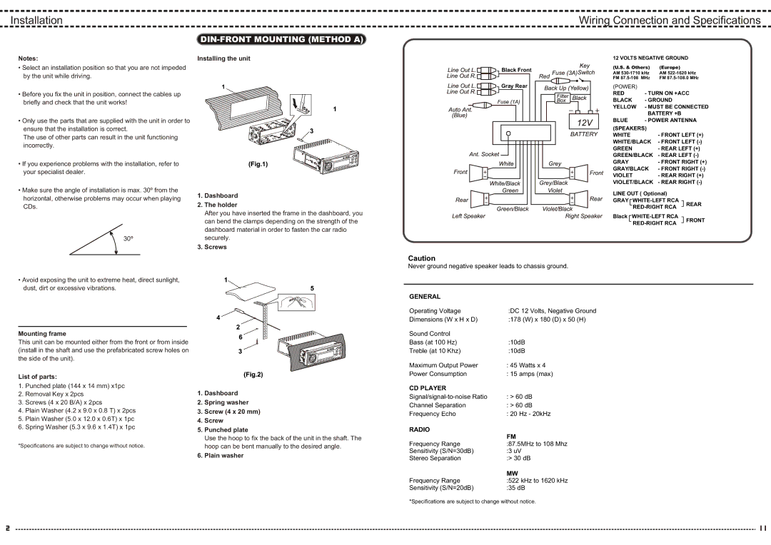
12 VOLTS NEGATIVE GROUND
•Select an installation position so that you are not impeded by the unit while driving.
•Before you fix the unit in position, connect the cables up briefly and check that the unit works!
•Only use the parts that are supplied with the unit in order to ensure that the installation is correct.
The use of other parts can result in the unit functioning incorrectly.
•If you experience problems with the installation, refer to your specialist dealer.
•Make sure the angle of installation is max. 30º from the horizontal, otherwise problems may occur when playing CDs.
30º
1.Dashboard
2.The holder
After you have inserted the frame in the dashboard, you can bend the clamps depending on the strength of the dashboard material in order to fasten the car radio securely.
3.Screws
Black Front |
Gray Rear |
(U.S. & Others) | (Europe) |
AM | AM |
FM | FM |
(POWER) |
|
|
| ||||
RED | - TURN ON +ACC | ||||||
BLACK | - GROUND |
|
| ||||
YELLOW - MUST BE CONNECTED | |||||||
|
|
|
| BATTERY +B |
|
| |
BLUE | - POWER ANTENNA | ||||||
(SPEAKERS) |
|
|
| ||||
WHITE |
| - FRONT LEFT (+) | |||||
WHITE/BLACK | - FRONT LEFT | ||||||
GREEN |
| - REAR LEFT (+) | |||||
GREEN/BLACK | - REAR LEFT | ||||||
GRAY |
| - FRONT RIGHT (+) | |||||
GRAY/BLACK | - FRONT RIGHT | ||||||
VIOLET |
| - REAR RIGHT (+) | |||||
VIOLET/BLACK | - REAR RIGHT | ||||||
LINE OUT ( Optional) |
|
| |||||
GRAY |
|
| REAR | ||||
|
| ||||||
|
|
|
|
|
| ||
Black |
|
| FRONT | ||||
|
| ||||||
|
|
|
|
|
| ||
•Avoid exposing the unit to extreme heat, direct sunlight, dust, dirt or excessive vibrations.
Mounting frame
This unit can be mounted either from the front or from inside (install in the shaft and use the prefabricated screw holes on the side of the unit).
Caution
Never ground negative speaker leads to chassis ground.
GENERAL |
|
Operating Voltage | :DC 12 Volts, Negative Ground |
Dimensions (W x H x D) | :178 (W) x 180 (D) x 50 (H) |
Sound Control |
|
Bass (at 100 Hz) | :10dB |
Treble (at 10 Khz) | :10dB |
Maximum Output Power | : 45 Watts x 4 |
Power Consumption | : 15 amps (max) |
List of parts:
1.Punched plate (144 x 14 mm) x1pc
2.Removal Key x 2pcs
3.Screws (4 x 20 B/A) x 2pcs
4.Plain Washer (4.2 x 9.0 x 0.8 T) x 2pcs
5.Plain Washer (5.0 x 12.0 x 0.6T) x 1pc
6.Spring Washer (5.3 x 9.6 x 1.4T) x 1pc
*Specifications are subject to change without notice.
1.Dashboard
2.Spring washer
3.Screw (4 x 20 mm)
4.Screw
5.Punched plate
Use the hoop to fix the back of the unit in the shaft. The hoop can be bent manually to the desired angle.
6.Plain washer
CD PLAYER |
|
: > 60 dB | |
Channel Separation | : > 60 dB |
Frequency Echo | : 20 Hz - 20kHz |
RADIO | FM |
| |
Frequency Range | :87.5MHz to 108 Mhz |
Sensitivity (S/N=30dB) | :3 uV |
Stereo Separation | :> 30 dB |
| MW |
Frequency Range | :522 kHz to 1620 kHz |
Sensitivity (S/N=20dB) | :35 dB |
*Specifications are subject to change without notice.