bolts finger tight. At this point the shift lever and shift lever spring are not against each other. As you tighten the bolts and nuts with two wrenches, these will pull together. See Figure 7.
•Tighten all hardware assembled to this point. Make sure that clutch grips are moving freely.
Attaching Control Cables
(Use Hardware E.)
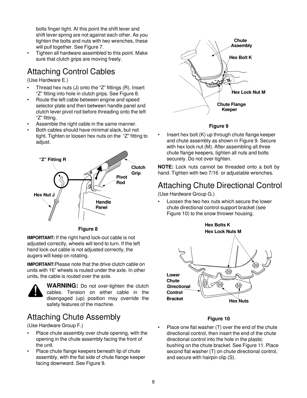
•Thread hex nuts (J) onto the “Z” fittings (R). Insert “Z” fitting into hole in clutch grips. See Figure 8.
•Route the left cable between engine and speed selector plate and then between handle panel and clutch lever pivot rod before threading onto the left “Z” fitting.
•Assemble the right cable in the same manner.
•Both cables should have minimal slack, but not tight. Tighten or loosen hex nuts on the “Z” fitting to adjust.
“Z” Fitting R
Clutch
Grip
Pivot
![]() Rod
Rod
Hex Nut J
Handle
Panel
Figure 8
IMPORTANT: If the right hand
IMPORTANT:Please note that the drive clutch cable on units with 16” wheels is routed under the axle. In other units, the cable is routed over the axle.
WARNING: Do not
Attaching Chute Assembly
(Use Hardware Group F.)
•Place chute assembly over chute opening, with the opening in the chute assembly facing the front of the unit.
•Place chute flange keepers beneath lip of chute assembly, with the flat side of chute flange keeper facing downward. See Figure 9.
Chute
Assembly
Hex Bolt K
Hex Lock Nut M
Chute Flange
Keeper
Figure 9
•Insert hex bolt (K) up through chute flange keeper and chute assembly as shown in Figure 9. Secure with hex lock nut (M). After assembling all three chute flange keepers, tighten all nuts and bolts securely. Do not
NOTE: Lock nuts cannot be threaded onto a bolt by hand. Tighten with two 7/16” or adjustable wrenches.
Attaching Chute Directional Control
(Use Hardware Group G.)
•Loosen the two hex nuts which secure the lower chute directional control support bracket (see Figure 10) to the snow thrower housing.
Hex Bolts K
Hex Lock Nuts M
Lower
Chute
Directional
Control
Bracket | Hex Nuts |
|
Figure 10
•Place one flat washer (T) over the end of the chute directional control, then insert the end of the chute directional control into the hole in the plastic bushing on the chute bracket. See Figure 11. Place second flat washer (T) on chute directional control, and secure with hairpin clip (S).
8