PRE-INSTALLATION CHECKS

It is important that adequate ventilation exists and the Flue or Chimney system that is to be used is in good working condition. Products of combustion that enter the room could be a serious health risk. Before installation of this product the Flue or Chimney system and Ventilation requirements are inspected by a competent person, and passed as suitable for use with the appliance to be fitted. In particular the following should be checked: -

1. Flue or Chimney

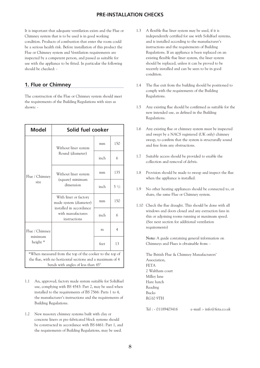
The construction of the Flue or Chimney system should meet the requirements of the Building Regulations with sizes as shown: -

Model

Solid fuel cooker


Without liner system

mm


150


Round (diameter)


inch


6


Flue / Chimney

Without liner system

mm


135

size

(square) minimum


inch


5 1/2


dimension


With liner or factory

mm


150


made system (diameter)


installed in accordance


inch


6


with manufactures


instructions


Flue / Chimney


m


4

minimum


feet


13

height *


*When measured from the top of the cooker to the


top of


the flue, with no horizontal sections and a maximum of 4

bends with angles of less than 45°


1.1An, approved, factory made system suitable for Solidfuel use, complying with BS 4543: Part 2, may be used when installed to the requirements of BS 7566: Parts 1 to 4, the manufacturer’s instructions and the requirements of Building Regulations.

1.2New masonry chimney systems built with clay or concrete liners or pre-fabricated block systems should be constructed in accordance with BS 6461: Part 1, and the requirements of Building Regulations, may be used.

1.3A flexible flue liner system may be used, if it is independently certified for use with Solidfuel systems, and is installed according to the manufacturer’s instructions and the requirements of Building Regulations. If an appliance is been replaced on an existing flexible flue liner system, the liner system should be replaced, unless it can be proved to be recently installed and can be seen to be in good condition.

1.4The flue exit from the building should be positioned to comply with the requirements of the Building Regulations.

1.5Any existing flue should be confirmed as suitable for the new intended use, as defined in the Building Regulations.

1.6Any existing flue or chimney system must be inspected and swept by a NACS registered (UK only) chimney sweep, to confirm that the system is structurally sound and free from any obstructions.

1.7Suitable access should be provided to enable the collection and removal of debris.

1.8Provision should be made to sweep and inspect the flue when the appliance is installed.

1.9No other heating appliances should be connected to, or share, the same Flue or Chimney system.

1.10Check the flue draught. This should be done with all windows and doors closed and any extraction fans in this or adjoining rooms running at maximum speed.

(See next section for additional ventilation requirements)

Note: A guide containing general information on

Chimneys and Flues is obtainable from: -

The British Flue & Chimney Manufacturers’ Association,

FETA

2 Waltham court Milley lane Hare hatch Reading Bucks

RG10 9TH

Tel : - 01189403416 e-mail :- info@feta.co.uk

8

Page 8
Image 8
Yeoman YM-CKWDWH-L, YM-CKWDPB-R, YM-CKWDGR-L, YM-CKWDWH-R, YM-CKWDGR-R, YM-CKWDBL-L, YM-CKWDPB-L, YM-CKWDBL-R Flue or Chimney

YM-CKWDBL-R, YM-CKWDPB-L, YM-CKWDBL-L, YM-CKWDGR-R, YM-CKWDWH-R specifications

The Yeoman YM-CKWDWH-L, YM-CKWDPB-R, YM-CKWDGR-L, YM-CKWDWH-R, and YM-CKWDGR-R are innovative devices designed to enhance operational efficiency and user experience across various industries. Each model comes equipped with advanced technologies that set them apart in their respective categories.

The YM-CKWDWH-L is characterized by its lightweight design and robust functionality. This model integrates cutting-edge sensors that monitor environmental conditions, making it suitable for outdoor applications. Its high-precision data collection capabilities ensure accuracy in real-time data analysis, beneficial for users in sectors such as agriculture, meteorology, and logistics.

On the other hand, the YM-CKWDPB-R is optimized for industrial use, featuring enhanced durability and superior performance. It employs a unique power management system that extends its operational lifespan, which is crucial for environments where continuous operation is mandatory. Moreover, it includes a user-friendly interface designed to facilitate easy navigation and control.

The YM-CKWDGR-L, distinguished by its green technology, is an environmentally conscious choice for users looking to reduce their carbon footprint. It operates on renewable energy sources and incorporates energy-efficient components, making it an attractive option for organizations committed to sustainability.

In contrast, the YM-CKWDWH-R offers advanced wireless connectivity features that allow seamless integration with existing systems. This model supports various communication protocols, ensuring compatibility with a wide range of devices. Its adaptability makes it ideal for businesses seeking to upgrade their infrastructure without undergoing extensive overhauls.

Lastly, the YM-CKWDGR-R combines innovation with resilience. Engineered with rugged materials, it withstands challenging conditions without compromising performance. This model is particularly well-suited for sectors that require reliability in harsh environments, such as construction and emergency services.

In summary, the Yeoman YM-CKWDWH-L, YM-CKWDPB-R, YM-CKWDGR-L, YM-CKWDWH-R, and YM-CKWDGR-R offer a diverse range of features tailored to meet varying user needs. From lightweight designs and energy efficiency to advanced connectivity and durability, these models cater to industries looking for efficiency, reliability, and innovation in their operations.