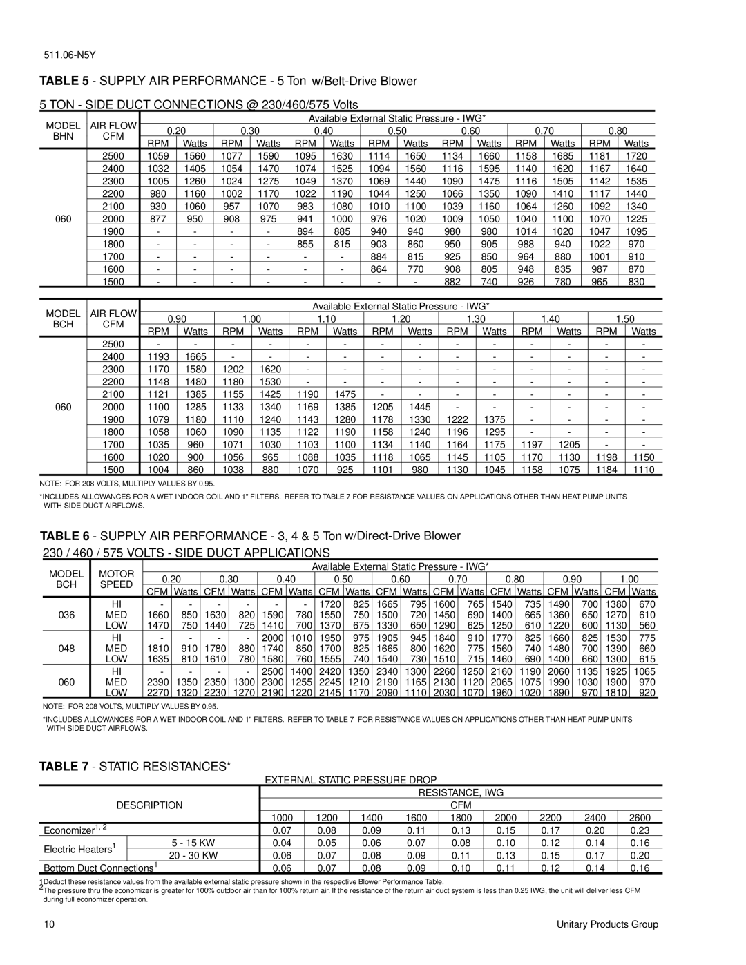
TABLE 5 - SUPPLY AIR PERFORMANCE - 5 Ton
MODEL | AIR FLOW |
|
|
|
|
|
| Available External Static Pressure - IWG* |
|
|
|
|
|
|
|
|
| ||||||||||
0.20 | 0.30 | 0.40 | 0.50 | 0.60 | 0.70 | 0.80 |
| ||||||||||||||||||||
BHN | CFM |
| |||||||||||||||||||||||||
RPM | Watts | RPM |
| Watts |
| RPM |
| Watts |
| RPM |
| Watts |
| RPM |
| Watts |
| RPM |
| Watts |
| RPM | Watts | ||||
|
|
|
|
|
|
|
|
|
|
|
| ||||||||||||||||
| 2500 | 1059 | 1560 | 1077 | 1590 | 1095 | 1630 | 1114 | 1650 | 1134 | 1660 | 1158 | 1685 | 1181 | 1720 |
| |||||||||||
| 2400 | 1032 | 1405 | 1054 | 1470 | 1074 | 1525 | 1094 | 1560 | 1116 | 1595 | 1140 | 1620 | 1167 | 1640 |
| |||||||||||
| 2300 | 1005 | 1260 | 1024 | 1275 | 1049 | 1370 | 1069 | 1440 | 1090 | 1475 | 1116 | 1505 | 1142 | 1535 |
| |||||||||||
| 2200 | 980 | 1160 | 1002 | 1170 | 1022 | 1190 | 1044 | 1250 | 1066 | 1350 | 1090 | 1410 | 1117 | 1440 |
| |||||||||||
| 2100 | 930 | 1060 | 957 | 1070 | 983 | 1080 | 1010 | 1100 | 1039 | 1160 | 1064 | 1260 | 1092 | 1340 |
| |||||||||||
060 | 2000 | 877 | 950 | 908 | 975 | 941 | 1000 | 976 | 1020 | 1009 | 1050 | 1040 | 1100 | 1070 | 1225 |
| |||||||||||
| 1900 | - | - | - | - | 894 | 885 | 940 | 940 | 980 | 980 | 1014 | 1020 | 1047 | 1095 |
| |||||||||||
| 1800 | - | - | - | - | 855 | 815 | 903 | 860 | 950 | 905 | 988 | 940 | 1022 | 970 |
| |||||||||||
| 1700 | - | - | - | - | - | - | 884 | 815 | 925 | 850 | 964 | 880 | 1001 | 910 |
| |||||||||||
| 1600 | - | - | - | - | - | - | 864 | 770 | 908 | 805 | 948 | 835 | 987 | 870 |
| |||||||||||
| 1500 | - | - | - | - | - | - | - | - | 882 | 740 | 926 | 780 | 965 | 830 |
| |||||||||||
|
|
|
|
|
|
|
|
|
|
|
|
|
|
|
|
|
|
|
|
|
|
| |||||
MODEL | AIR FLOW |
|
|
|
|
|
| Available External Static Pressure - IWG* |
|
|
|
|
|
|
|
|
| ||||||||||
0.90 | 1.00 |
| 1.10 |
| 1.20 |
| 1.30 |
| 1.40 |
| 1.50 |
| |||||||||||||||
BCH | CFM |
|
|
|
|
|
| ||||||||||||||||||||
RPM | Watts | RPM |
| Watts |
| RPM |
| Watts |
| RPM |
| Watts |
| RPM |
| Watts |
| RPM |
| Watts |
| RPM |
| Watts | |||
|
|
|
|
|
|
|
|
|
|
|
|
| |||||||||||||||
| 2500 | - | - | - |
| - |
| - |
| - |
| - |
| - |
| - |
| - |
| - |
| - |
| - |
| - |
|
| 2400 | 1193 | 1665 | - |
| - |
| - |
| - |
| - |
| - |
| - |
| - |
| - |
| - |
| - |
| - |
|
| 2300 | 1170 | 1580 | 1202 |
| 1620 |
| - |
| - |
| - |
| - |
| - |
| - |
| - |
| - |
| - |
| - |
|
| 2200 | 1148 | 1480 | 1180 |
| 1530 |
| - |
| - |
| - |
| - |
| - |
| - |
| - |
| - |
| - |
| - |
|
| 2100 | 1121 | 1385 | 1155 |
| 1425 |
| 1190 |
| 1475 |
| - |
| - |
| - |
| - |
| - |
| - |
| - |
| - |
|
060 | 2000 | 1100 | 1285 | 1133 |
| 1340 |
| 1169 |
| 1385 |
| 1205 |
| 1445 |
| - |
| - |
| - |
| - |
| - |
| - |
|
| 1900 | 1079 | 1180 | 1110 |
| 1240 |
| 1143 |
| 1280 |
| 1178 |
| 1330 |
| 1222 |
| 1375 |
| - |
| - |
| - |
| - |
|
| 1800 | 1058 | 1060 | 1090 |
| 1135 |
| 1122 |
| 1190 |
| 1158 |
| 1240 |
| 1196 |
| 1295 |
| - |
| - |
| - |
| - |
|
| 1700 | 1035 | 960 | 1071 |
| 1030 |
| 1103 |
| 1100 |
| 1134 |
| 1140 |
| 1164 |
| 1175 |
| 1197 |
| 1205 |
| - |
| - |
|
| 1600 | 1020 | 900 | 1056 |
| 965 |
| 1088 |
| 1035 |
| 1118 |
| 1065 |
| 1145 |
| 1105 |
| 1170 |
| 1130 |
| 1198 |
| 1150 |
|
| 1500 | 1004 | 860 | 1038 |
| 880 |
| 1070 |
| 925 |
| 1101 |
| 980 |
| 1130 |
| 1045 |
| 1158 |
| 1075 |
| 1184 |
| 1110 |
|
NOTE: FOR 208 VOLTS, MULTIPLY VALUES BY 0.95.
*INCLUDES ALLOWANCES FOR A WET INDOOR COIL AND 1" FILTERS. REFER TO TABLE 7 FOR RESISTANCE VALUES ON APPLICATIONS OTHER THAN HEAT PUMP UNITS WITH SIDE DUCT AIRFLOWS.
TABLE 6 - SUPPLY AIR PERFORMANCE - 3, 4 & 5 Ton
MODEL | MOTOR |
|
|
|
|
| Available External Static Pressure - IWG* |
|
|
|
|
|
| ||||||||
0.20 | 0.30 | 0.40 | 0.50 | 0.60 | 0.70 |
| 0.80 | 0.90 | 1.00 | ||||||||||||
BCH | SPEED |
| |||||||||||||||||||
CFM | Watts | CFM | Watts | CFM | Watts | CFM | Watts | CFM | Watts | CFM | Watts | CFM | Watts | CFM | Watts | CFM | Watts | ||||
|
| ||||||||||||||||||||
| HI | - | - | - | - | - | - | 1720 | 825 | 1665 | 795 | 1600 | 765 |
| 1540 | 735 | 1490 | 700 | 1380 | 670 | |
036 | MED | 1660 | 850 | 1630 | 820 | 1590 | 780 | 1550 | 750 | 1500 | 720 | 1450 | 690 |
| 1400 | 665 | 1360 | 650 | 1270 | 610 | |
| LOW | 1470 | 750 | 1440 | 725 | 1410 | 700 | 1370 | 675 | 1330 | 650 | 1290 | 625 |
| 1250 | 610 | 1220 | 600 | 1130 | 560 | |
| HI | - | - | - | - | 2000 | 1010 | 1950 | 975 | 1905 | 945 | 1840 | 910 |
| 1770 | 825 | 1660 | 825 | 1530 | 775 | |
048 | MED | 1810 | 910 | 1780 | 880 | 1740 | 850 | 1700 | 825 | 1665 | 800 | 1620 | 775 |
| 1560 | 740 | 1480 | 700 | 1390 | 660 | |
| LOW | 1635 | 810 | 1610 | 780 | 1580 | 760 | 1555 | 740 | 1540 | 730 | 1510 | 715 |
| 1460 | 690 | 1400 | 660 | 1300 | 615 | |
| HI | - | - | - | - | 2500 | 1400 | 2420 | 1350 | 2340 | 1300 | 2260 | 1250 |
| 2160 | 1190 | 2060 | 1135 | 1925 | 1065 | |
060 | MED | 2390 | 1350 | 2350 | 1300 | 2300 | 1255 | 2245 | 1210 | 2190 | 1165 | 2130 | 1120 |
| 2065 | 1075 | 1990 | 1030 | 1900 | 970 | |
| LOW | 2270 | 1320 | 2230 | 1270 | 2190 | 1220 | 2145 | 1170 | 2090 | 1110 | 2030 | 1070 |
| 1960 | 1020 | 1890 | 970 | 1810 | 920 | |
NOTE: FOR 208 VOLTS, MULTIPLY VALUES BY 0.95.
*INCLUDES ALLOWANCES FOR A WET INDOOR COIL AND 1" FILTERS. REFER TO TABLE 7 FOR RESISTANCE VALUES ON APPLICATIONS OTHER THAN HEAT PUMP UNITS WITH SIDE DUCT AIRFLOWS.
TABLE 7 - STATIC RESISTANCES*
EXTERNAL STATIC PRESSURE DROP
|
|
|
|
|
| RESISTANCE, IWG |
|
|
| ||
| DESCRIPTION |
|
|
|
| CFM |
|
|
|
| |
|
|
| 1000 | 1200 | 1400 | 1600 | 1800 | 2000 | 2200 | 2400 | 2600 |
Economizer1, 2 |
|
| 0.07 | 0.08 | 0.09 | 0.11 | 0.13 | 0.15 | 0.17 | 0.20 | 0.23 |
Electric Heaters1 |
| 5 - 15 KW | 0.04 | 0.05 | 0.06 | 0.07 | 0.08 | 0.10 | 0.12 | 0.14 | 0.16 |
| 20 - 30 KW | 0.06 | 0.07 | 0.08 | 0.09 | 0.11 | 0.13 | 0.15 | 0.17 | 0.20 | |
|
| ||||||||||
Bottom Duct Connections1 | 0.06 | 0.07 | 0.08 | 0.09 | 0.10 | 0.11 | 0.12 | 0.14 | 0.16 | ||
1Deduct these resistance values from the available external static pressure shown in the respective Blower Performance Table.
2The pressure thru the economizer is greater for 100% outdoor air than for 100% return air. If the resistance of the return air duct system is less than 0.25 IWG, the unit will deliver less CFM during full economizer operation.
10 | Unitary Products Group |