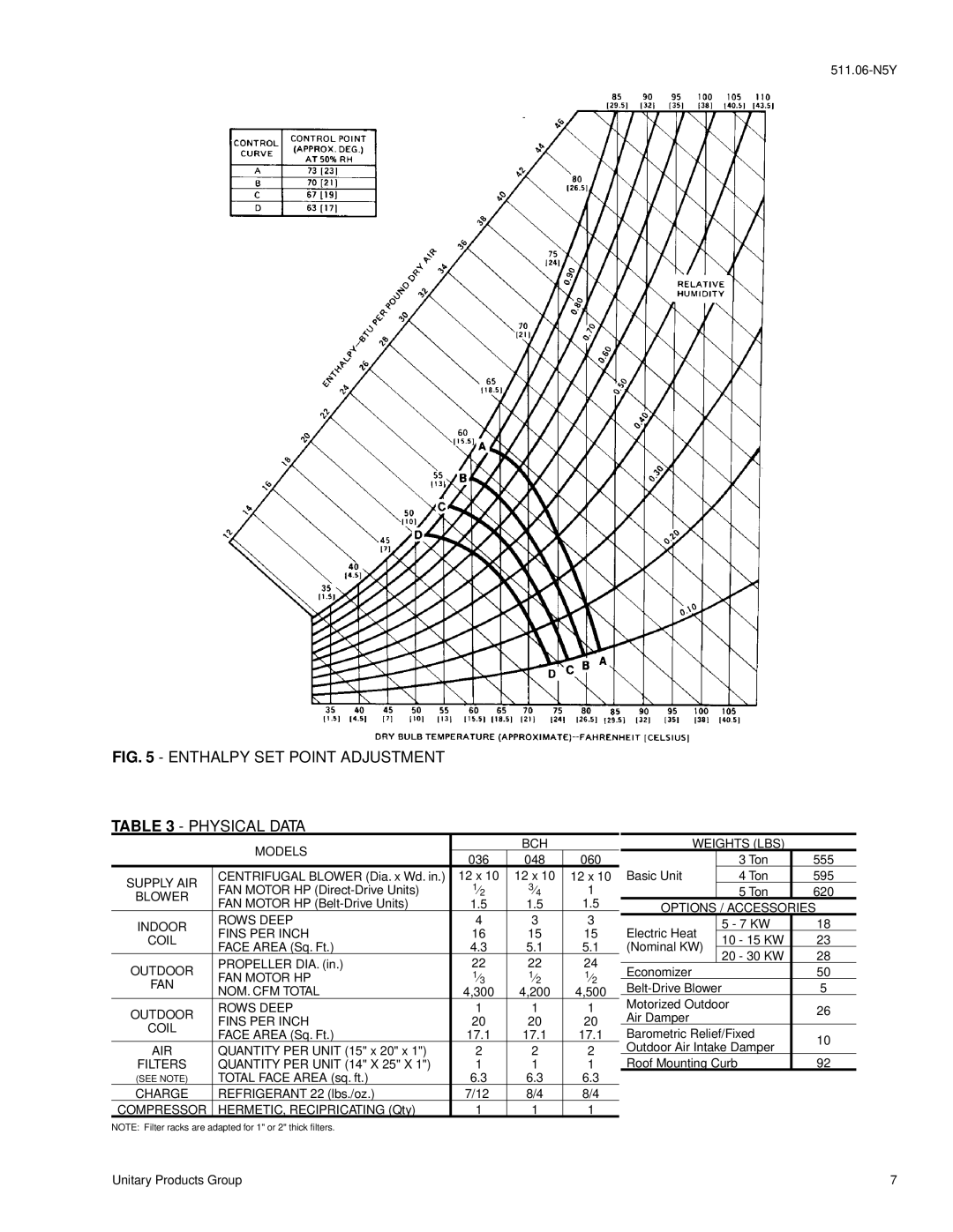
FIG. 5 - ENTHALPY SET POINT ADJUSTMENT
TABLE 3 - PHYSICAL DATA
| MODELS |
| BCH |
| |
| 036 | 048 | 060 | ||
|
| ||||
SUPPLY AIR | CENTRIFUGAL BLOWER (Dia. x Wd. in.) | 12 x 10 | 12 x 10 | 12 x 10 | |
FAN MOTOR HP | 1⁄2 | 3⁄4 | 1 | ||
BLOWER | |||||
FAN MOTOR HP | 1.5 | 1.5 | 1.5 | ||
| |||||
INDOOR | ROWS DEEP | 4 | 3 | 3 | |
FINS PER INCH | 16 | 15 | 15 | ||
COIL | |||||
FACE AREA (Sq. Ft.) | 4.3 | 5.1 | 5.1 | ||
| |||||
OUTDOOR | PROPELLER DIA. (in.) | 22 | 22 | 24 | |
FAN MOTOR HP | 1⁄3 | 1⁄2 | 1⁄2 | ||
FAN | |||||
NOM. CFM TOTAL | 4,300 | 4,200 | 4,500 | ||
| |||||
OUTDOOR | ROWS DEEP | 1 | 1 | 1 | |
FINS PER INCH | 20 | 20 | 20 | ||
COIL | |||||
FACE AREA (Sq. Ft.) | 17.1 | 17.1 | 17.1 | ||
| |||||
AIR | QUANTITY PER UNIT (15" x 20" x 1") | 2 | 2 | 2 | |
FILTERS | QUANTITY PER UNIT (14" X 25" X 1") | 1 | 1 | 1 | |
(SEE NOTE) | TOTAL FACE AREA (sq. ft.) | 6.3 | 6.3 | 6.3 | |
CHARGE | REFRIGERANT 22 (lbs./oz.) | 7/12 | 8/4 | 8/4 | |
COMPRESSOR | HERMETIC, RECIPRICATING (Qty) | 1 | 1 | 1 |
WEIGHTS (LBS)
|
| 3 Ton | 555 | |
Basic Unit |
| 4 Ton | 595 | |
|
| 5 Ton | 620 | |
OPTIONS / ACCESSORIES | ||||
Electric Heat |
| 5 - 7 KW | 18 | |
| 10 - 15 KW | 23 | ||
(Nominal KW) |
| |||
| 20 - 30 KW | 28 | ||
|
| |||
Economizer |
| 50 | ||
| 5 | |||
Motorized Outdoor | 26 | |||
Air Damper |
| |||
|
| |||
Barometric Relief/Fixed | 10 | |||
Outdoor Air Intake Damper | ||||
| ||||
Roof Mounting Curb | 92 | |||
NOTE: Filter racks are adapted for 1" or 2" thick filters.
Unitary Products Group | 7 |