OPERATION
COOLING SYSTEM
The unit has an
The compressor is hermetically sealed, internally sprung, mounted on spring isolators and inherently (internally) protected. If there is an abnormal temperature rise in the compressor, the protector will open to shut down the compressor.
PRELIMINARY OPERATION COOLING
After the installation has been completed, the crankcase heater of the compressor must be energized for at least 4 hours before starting the unit. After this initial
NOTE: Prior to each cooling season, the crankcase heater must be energized at least 10 hours before the system is put into operation.
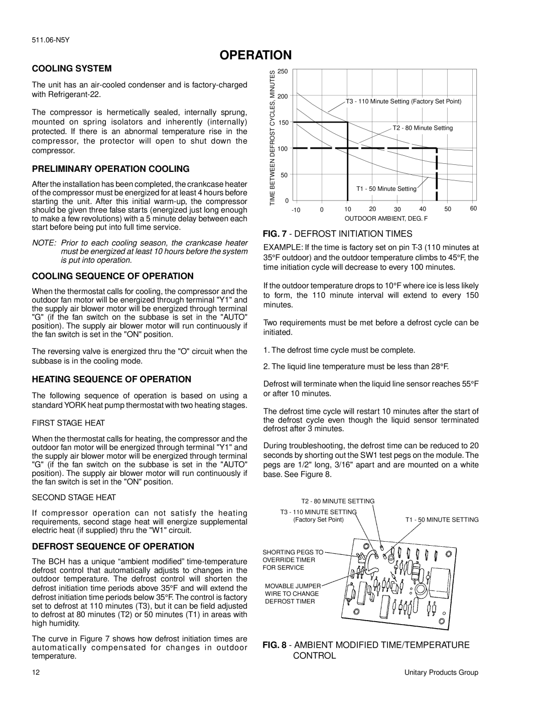
MINUTES | 250 |
|
|
|
|
|
|
| |
200 |
| T3 - 110 Minute Setting (Factory Set Point) |
| ||||||
CYCLES, |
|
| |||||||
|
|
| |||||||
150 |
|
|
| T2 - 80 Minute Setting |
| ||||
DEFROST |
|
|
|
|
| ||||
100 |
|
|
|
|
|
|
| ||
|
|
|
|
|
|
|
| ||
BETWEEN | 50 |
|
|
|
|
|
|
| |
|
|
| T1 - 50 Minute Setting |
|
|
| |||
TIME |
|
|
|
|
|
| |||
0 |
|
|
|
|
|
|
| ||
0 | 10 | 20 | 30 | 40 | 50 | 60 | |||
| |||||||||
|
|
| OUTDOOR AMBIENT, DEG. F |
|
| ||||
FIG. 7 - DEFROST INITIATION TIMES
EXAMPLE: If the time is factory set on pin
COOLING SEQUENCE OF OPERATION
When the thermostat calls for cooling, the compressor and the outdoor fan motor will be energized through terminal "Y1" and the supply air blower motor will be energized through terminal "G" (if the fan switch on the subbase is set in the "AUTO" position). The supply air blower motor will run continuously if the fan switch is set in the "ON" position.
The reversing valve is energized thru the "O" circuit when the subbase is in the cooling mode.
HEATING SEQUENCE OF OPERATION
The following sequence of operation is based on using a standard YORK heat pump thermostat with two heating stages.
FIRST STAGE HEAT
When the thermostat calls for heating, the compressor and the outdoor fan motor will be energized through terminal "Y1" and the supply air blower motor will be energized through terminal "G" (if the fan switch on the subbase is set in the "AUTO" position). The supply air blower motor will run continuously if the fan switch is set in the "ON" position.
SECOND STAGE HEAT
If compressor operation can not satisfy the heating requirements, second stage heat will energize supplemental electric heat (if supplied) thru the "W1" circuit.
DEFROST SEQUENCE OF OPERATION
The BCH has a unique “ambient modified”
The curve in Figure 7 shows how defrost initiation times are automatically compensated for changes in outdoor temperature.
If the outdoor temperature drops to 10° F where ice is less likely to form, the 110 minute interval will extend to every 150 minutes.
Two requirements must be met before a defrost cycle can be initiated.
1.The defrost time cycle must be complete.
2.The liquid line temperature must be less than 28° F.
Defrost will terminate when the liquid line sensor reaches 55° F or after 10 minutes.
The defrost time cycle will restart 10 minutes after the start of the defrost cycle even though the liquid sensor terminated defrost after 3 minutes.
During troubleshooting, the defrost time can be reduced to 20 seconds by shorting out the SW1 test pegs on the module. The pegs are 1/2" long, 3/16" apart and are mounted on a white base. See Figure 8.
T2 - 80 MINUTE SETTING |
|
T3 - 110 MINUTE SETTING |
|
(Factory Set Point) | T1 - 50 MINUTE SETTING |
SHORTING PEGS TO
OVERRIDE TIMER
FOR SERVICE
MOVABLE JUMPER
WIRE TO CHANGE
DEFROST TIMER
FIG. 8 - AMBIENT MODIFIED TIME/TEMPERATURE CONTROL
12 | Unitary Products Group |