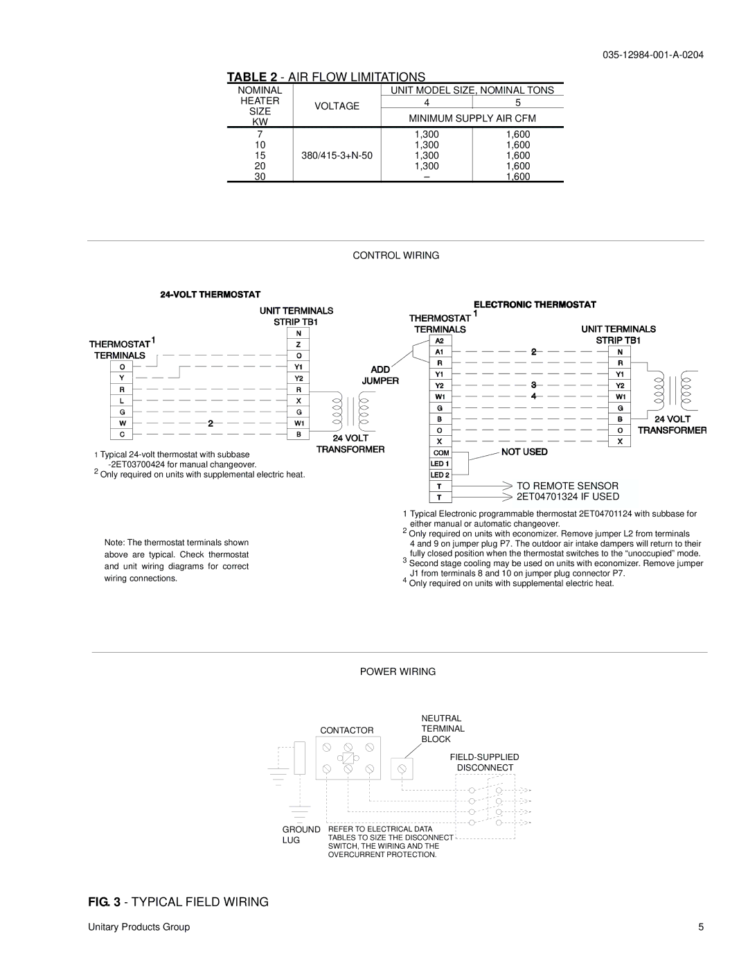
B3CH 048 and 060 specifications
The York B3CH 048 and 060 are part of the advanced line of commercial rooftop units by York, known for their reliability and energy efficiency. Specifically designed for medium to large commercial applications, these units are engineered to provide optimal performance while minimizing operational costs.One of the key features of the York B3CH series is its adaptable cooling capacity. The B3CH 048 has a cooling capacity of 48,000 BTU/h, while the B3CH 060 offers a slightly higher capacity of 60,000 BTU/h. This flexibility allows businesses to select the unit that best meets their specific cooling requirements, ensuring comfort and efficiency in any environment.
Both models utilize a highly efficient scroll compressor, which is known for its durability and quiet operation. The scroll compressor design allows for superior performance in varying load conditions, contributing to better energy efficiency. In addition, the units feature a multi-speed motor design that adjusts airflow based on demand, further enhancing performance and reducing energy consumption.
York has incorporated advanced technologies into the B3CH series to ensure reliability and ease of maintenance. These units come equipped with a smart control system that enhances user interface through advanced diagnostics and monitoring capabilities. The control system enables users to program temperature settings efficiently and oversees system operation to prevent potential issues. The built-in diagnostic features help facilitate quicker troubleshooting, minimizing downtime.
The units are designed with a robust and weather-resistant cabinet, ensuring durability in various environmental conditions. The galvanized steel construction aids in corrosion resistance, leading to a longer lifespan for the units. Additionally, both models are equipped with high-efficiency air filters that not only improve indoor air quality but also extend the life of the system by minimizing dust accumulation.
Energy efficiency is a significant consideration in today's commercial environments, and the York B3CH series excels in this aspect. With competitive SEER and EER ratings, these units not only comply with but often exceed industry standards, resulting in lower energy bills and reduced carbon footprints.
In summary, the York B3CH 048 and 060 are cutting-edge rooftop units that combine performance, reliability, and energy efficiency. They are ideal for businesses seeking effective solutions for climate control while maintaining operational and energy costs at a minimum.

