K4EU120A50A, K5EU090A50A specifications
The York K4EU120A50A and K5EU090A50A are high-performance commercial air conditioning units designed for efficiency and reliability. These models integrate advanced technology to meet the demanding cooling needs of various commercial spaces.One of the primary features of the K4EU120A50A is its high capacity cooling ability, rated at 120,000 BTU, making it ideal for medium to large commercial environments such as office buildings, retail stores, and warehouses. The K5EU090A50A offers a slightly lower capacity of 90,000 BTU, suitable for smaller commercial areas or specific zoned applications within larger buildings. Both units are equipped with energy-efficient compressors that ensure optimal performance while reducing overall energy consumption.
The K4EU and K5EU series utilize variable speed technology, which allows the units to adjust their cooling output based on the space's specific requirements. This feature not only enhances comfort by maintaining consistent temperatures but also contributes to lower operating costs. The inverter-driven compressor technology further enhances energy efficiency by continuously adjusting the cooling output to match the varying demands of the environment.
Both models include advanced air filtration systems designed to improve indoor air quality. The filters capture dust, pollen, and other airborne particles, promoting a healthier atmosphere for occupants. Additionally, the units feature a robust and corrosion-resistant cabinet design, ensuring durability even in harsh conditions.
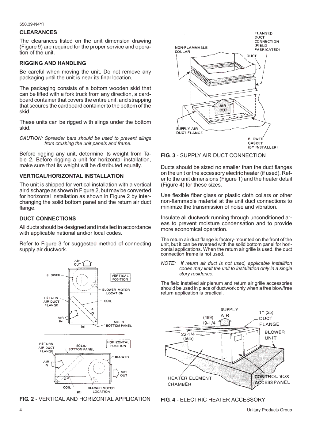
Installation flexibility is another strong point of the K4EU and K5EU series. These units can be installed in various configurations, including rooftop, ground level, or wall-mounted setups, accommodating different building designs and layouts. The user-friendly control system allows for easy adjustments and monitoring, providing real-time data on performance and energy usage.
The York K4EU120A50A and K5EU090A50A models are also designed with quiet operation in mind. The sound-attenuating components reduce noise levels, making them suitable for environments where noise can be a concern.
In summary, the York K4EU120A50A and K5EU090A50A are distinguished by their high cooling capacities, energy efficiency, advanced technology, and enhanced indoor air quality features. They provide reliable cooling solutions tailored to the needs of commercial users, ensuring comfort and sustainability in a variety of settings.

