550.39-N4YI

Before brazing the refrigerant lines to these connections, remove the short panel from the unit frame and slide it (along with the grommets) onto the refrigerant lines. Af- ter the brazed joints have cooled, slide the panel back into place and secure it to the unit frame.

NOTE: These units can only be piped from one side of the unit.

EXPANSION VALVE BULB

On KEU090 units the expansion valve bulb must be fas- tened in a 4 o'clock position to the suction line outside the cabinet after the piping connections have been made.

On KEU120 units fasten the expansion valve bulb on the suction header 8" (203mm) below the top of the header and adjacent to the coil.

Use the clamps provided with the valve to secure the bulb in position.

DRAIN CONNECTION

The drain line MUST be trapped because the coil is lo- cated on the negative side of the supply air blower. It must also be protected from freezing temperatures.

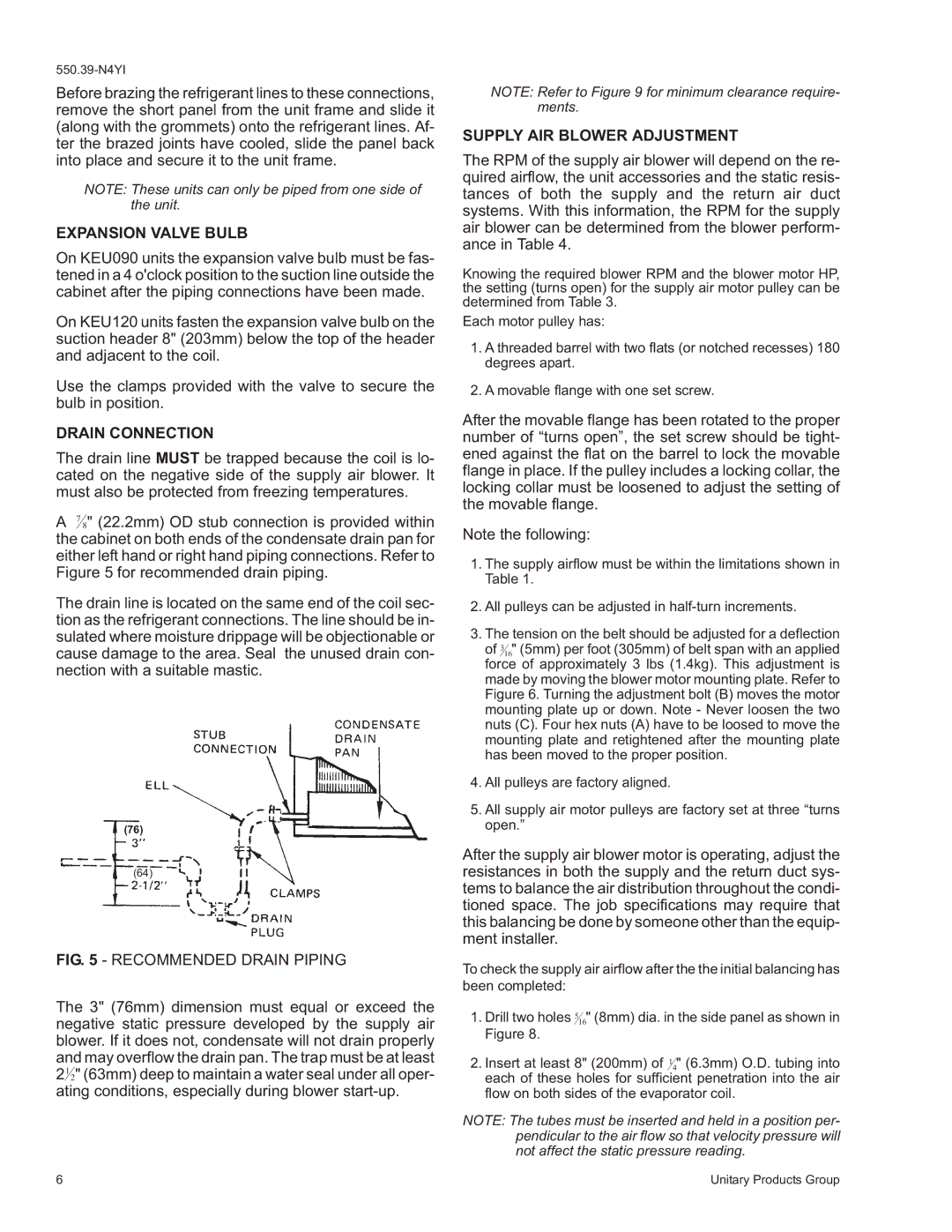
A 7 8" (22.2mm) OD stub connection is provided within the cabinet on both ends of the condensate drain pan for either left hand or right hand piping connections. Refer to Figure 5 for recommended drain piping.

The drain line is located on the same end of the coil sec- tion as the refrigerant connections. The line should be in- sulated where moisture drippage will be objectionable or cause damage to the area. Seal the unused drain con- nection with a suitable mastic.

(76)

(64)

FIG. 5 - RECOMMENDED DRAIN PIPING

The 3" (76mm) dimension must equal or exceed the negative static pressure developed by the supply air blower. If it does not, condensate will not drain properly and may overflow the drain pan. The trap must be at least 212" (63mm) deep to maintain a water seal under all oper- ating conditions, especially during blower start-up.

NOTE: Refer to Figure 9 for minimum clearance require- ments.

SUPPLY AIR BLOWER ADJUSTMENT

The RPM of the supply air blower will depend on the re- quired airflow, the unit accessories and the static resis- tances of both the supply and the return air duct systems. With this information, the RPM for the supply air blower can be determined from the blower perform- ance in Table 4.

Knowing the required blower RPM and the blower motor HP, the setting (turns open) for the supply air motor pulley can be determined from Table 3.

Each motor pulley has:

1.A threaded barrel with two flats (or notched recesses) 180 degrees apart.

2.A movable flange with one set screw.

After the movable flange has been rotated to the proper number of “turns open”, the set screw should be tight- ened against the flat on the barrel to lock the movable flange in place. If the pulley includes a locking collar, the locking collar must be loosened to adjust the setting of the movable flange.

Note the following:

1.The supply airflow must be within the limitations shown in Table 1.

2.All pulleys can be adjusted in half-turn increments.

3.The tension on the belt should be adjusted for a deflection

of 316" (5mm) per foot (305mm) of belt span with an applied force of approximately 3 lbs (1.4kg). This adjustment is made by moving the blower motor mounting plate. Refer to Figure 6. Turning the adjustment bolt (B) moves the motor mounting plate up or down. Note - Never loosen the two nuts (C). Four hex nuts (A) have to be loosed to move the mounting plate and retightened after the mounting plate has been moved to the proper position.

4.All pulleys are factory aligned.

5.All supply air motor pulleys are factory set at three “turns open.”

After the supply air blower motor is operating, adjust the resistances in both the supply and the return duct sys- tems to balance the air distribution throughout the condi- tioned space. The job specifications may require that this balancing be done by someone other than the equip- ment installer.

To check the supply air airflow after the the initial balancing has been completed:

1.Drill two holes 516" (8mm) dia. in the side panel as shown in Figure 8.

2.Insert at least 8" (200mm) of 14" (6.3mm) O.D. tubing into each of these holes for sufficient penetration into the air flow on both sides of the evaporator coil.

NOTE: The tubes must be inserted and held in a position per- pendicular to the air flow so that velocity pressure will not affect the static pressure reading.

6

Unitary Products Group

Page 6
Image 6
York K5EU090A50A, K4EU120A50A installation instructions Expansion Valve Bulb, Drain Connection, Supply AIR Blower Adjustment

K4EU120A50A, K5EU090A50A specifications

The York K4EU120A50A and K5EU090A50A are high-performance commercial air conditioning units designed for efficiency and reliability. These models integrate advanced technology to meet the demanding cooling needs of various commercial spaces.

One of the primary features of the K4EU120A50A is its high capacity cooling ability, rated at 120,000 BTU, making it ideal for medium to large commercial environments such as office buildings, retail stores, and warehouses. The K5EU090A50A offers a slightly lower capacity of 90,000 BTU, suitable for smaller commercial areas or specific zoned applications within larger buildings. Both units are equipped with energy-efficient compressors that ensure optimal performance while reducing overall energy consumption.

The K4EU and K5EU series utilize variable speed technology, which allows the units to adjust their cooling output based on the space's specific requirements. This feature not only enhances comfort by maintaining consistent temperatures but also contributes to lower operating costs. The inverter-driven compressor technology further enhances energy efficiency by continuously adjusting the cooling output to match the varying demands of the environment.

Both models include advanced air filtration systems designed to improve indoor air quality. The filters capture dust, pollen, and other airborne particles, promoting a healthier atmosphere for occupants. Additionally, the units feature a robust and corrosion-resistant cabinet design, ensuring durability even in harsh conditions.

Installation flexibility is another strong point of the K4EU and K5EU series. These units can be installed in various configurations, including rooftop, ground level, or wall-mounted setups, accommodating different building designs and layouts. The user-friendly control system allows for easy adjustments and monitoring, providing real-time data on performance and energy usage.

The York K4EU120A50A and K5EU090A50A models are also designed with quiet operation in mind. The sound-attenuating components reduce noise levels, making them suitable for environments where noise can be a concern.

In summary, the York K4EU120A50A and K5EU090A50A are distinguished by their high cooling capacities, energy efficiency, advanced technology, and enhanced indoor air quality features. They provide reliable cooling solutions tailored to the needs of commercial users, ensuring comfort and sustainability in a variety of settings.