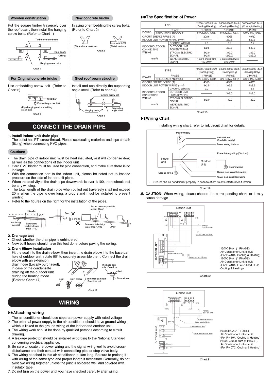
York YOCC-YOHC 12-60 Connect The Drain Pipe, The Specification of Power, Wiring Chart

Models: YOCC-YOHC 12-60

1 8
Download 8 pages 50.54 Kb
Page 4
Image 4
❥✱The Specification of Power
Seal
The base pan hole of outdoor

Wooden construction

Put the square timber traversely over the roof beam, then install the hanging screw bolts. (Refer to Chart 1)

Timber over the beam

Roof beam

Ceiling

Hanging screw bolts

Chart 1

New concrete bricks

Inlaying or embedding the screw bolts. (Refer to Chart 2)

(Blade shape insertion)

(Slide insertion)

Chart 2

❥✱The Specification of Power


TYPE

12000~18000 Btu/h

24000-36000 Btu/h

36000-60000 Btu/h


(Cooling&Heating)

(Cooling&Heating)

(Cooling&Heating)


POWER


PHASE


1-PHASE

1-PHASE


3-PHASE


FREQUENCY AND VOLT

220-240V~, 50Hz

220-240V~, 50Hz

380V 3N~, 50Hz


CIRCUIT BREAKER/FUSE (A)

20/16


40/25

40/20


INDOOR UNIT POWER WIRING (mm2)


3x2.5


5x2.5


GROUND WIRING

2.0


2.5

2.5


INDOOR/OUTDOOR


OUTDOOR UNIT


3x2.5

3x2.5


5x2.5

CONNECTING


POWER WIRING


WIRING


STRONG ELECTRIC


5x2.0

3x2.0


3x2.0


SIGNAL


(3x2.0)

(2x2.0)


(2x2.0)


(mm2)


WEAK ELECTRIC

1-core sheild wire

2-core sheild wire


SIGNAL


1x0.5mm2

2x0.5mm2


TYPE

12000~18000 Btu/h

24000-36000 Btu/h

36000-60000 Btu/h


(Cooling Only)

(Cooling Only)

(Cooling Only)


PHASE


1-PHASE

1-PHASE


3-PHASE

For Original concrete bricks

Use embedding screw bolt. (Refer to Chart 3)

❥✱Wiring Chart Steel bar

CONNECT THE DRAIN PIPEWIRING Embedding screw bolt

(Pipe hanging and embedding screw bolt)

Chart 3

Steel roof beam structre

Install and use directly the supporting angle steel. (Refer to chart 4)


Hanging screw bolt

Hanging bolts

Supporting

angle steel

Chart 4

POWER


FREQUENCY AND VOLT

220-240V~, 50Hz

220-240V~, 50Hz

380V 3N~, 50Hz


CIRCUIT BREAKER/FUSE (A)

40/25


40/20


40/25


INDOOR UNIT POWER WIRING (mm2)


3x2.5


3x2.5


5x2.5


GROUND WIRING

2.0


2.0


2.0


INDOOR/OUTDOOR

OUTDOOR UNIT


3x2.0


5x2.0

CONNECTING

POWER WIRING


WIRING


STRONG ELECTRIC


3x2.0


1x2.0


1x2.0


SIGNAL


(mm2)

WEAK ELECTRIC


SIGNAL


Chart 18

❥✱Wiring Chart

CONNECT THE DRAIN PIPE

Installing wiring chart, refer to link circuit chart for details.

1.Install indoor unit drain pipe

The outlet has PTI screw thread, Please use sealing materials and pipe sheath (fitting) when connecting PVC pipes.

Cautions

• The drain pipe of indoor unit must be heat insulated, or it will condense dew,

as well as the connections of the indoor unit.

• Hard PVC binder must be used for pipe connection, and make sure there is no

leakage.

• With the connection part to the indoor unit, please be noted not to impose

pressure on the side of indoor unit pipes.

Power supply

Indoor

Unit

Ground wiring

Outdoor Unit

Switch/Fuse (Available locally)

Power wiring (indoor)

Power linking wiring (Outdoor)

Ground wiring

Strong elec-signal link wiring Weak elec-signal link wiring

• When the declivity of the drain pipe downwards is over 1/100, there should not

be any winding.

• The total length of the drain pipe when pulled out traversely shall not exceed

20m, when the pipe is over long, a prop stand must be installed to prevent

winding.

• Refer to the figures on the right for the installation of the pipes.


Put as deep as possible


1.5m~2m

(about 10cm)


Bend


S shape


Insulating

Downward

Downward declivity


material


declivity lower

VP30


lower than 1/100


than 1/100


2. Drainage test

Check whether the drainpipe is unhindered

New built house should have this test done before paving the ceiling.

3.Drain Elbow Installation

Fit the seal into the drain elbow, then insert the drain elbow into the base pan hole of outdoor unit, rotate 90° to securely assemble them. Connect the drain elbow with an extension

drain hose (Locally purchased), in case of the condensate draining off the outdoor unit during the heating mode.

(Refer to Chart 17)

Seal

Drain elbow The base pan hole

Drain elbow


of outdoor unit


Chart 17


WIRING

❥✱Attaching wiring

1.The air conditioner should use separate power supply with rated voltage

2.The external power supply to the air conditioner should have ground wiring, which is linked to the ground wiring of the indoor and outdoor unit.

3.The wiring work should be done by qualified persons according to circuit drawing.

4.A leakage protector should be installed according to the National Standard concerning electrical appliance.

5.Be sure to locate the power wiring and the signal wring well to avoid cross- disturbance and their contact with connecting pipe or stop valve body.

6.The wiring attached to this air conditioner is 10m long. Be sure to prolong it with wiring of the same type and proper length if necessary. Generally, do not twist two wiring together unless the joint is soldered well and covered with insulator tape.

7.Do not turn on the power until you have checked carefully after wiring.

Ground the air conditioner properly in case to affect its anti-interference function

Chart 19

❥✱Attaching wiring CAUTION: When wiring, please choose the corresponding chart, or it may cause damage.


INDOOR UNIT


L N 1

2(N)


XT1

WHITE (T3)

BLACK (E)

XT2


Y&G


Y&G


POWER:


220-240V~50Hz


XT1


3-core cable 3x2.5mm2


UNIT

3 4


12000 Btu/h (1 PHASE)

OUTDOOR

1 N


5-core cable 5x2.0mm2


Air Conditioner Link-circuit


(For R-410A, Cooling & Heating)


1-core sheild wire 1x0.5mm2

E


18000 Btu/h (1 PHASE)


T3


Air Conditioner Link-circuit


XT2


(For R-410A, R-407C and R-22,


Cooling & Heating)


Chart 20

INDOOR UNIT


L N 1 2 3


XT1 T3

E XT2


Y&G


POWER:


220-240V~50Hz


Y&G


3-core cable 3x2.5mm2


UNIT

23


3-core cable 3x2.0mm2


3-core cable 3x2.5mm2


OUTDOOR

LN 1

E


24000Btu/h (1 PHASE)

1-core sheild wire 1x0.5mm2

Air Conditioner Link-circuit


XT1


(For R-410A, Cooling & Heating)


24000-36000Btu/h (1 PHASE)


Air Conditioner Link-circuit


T3


(For R-407C, Cooling & Heating)


XT2


Chart 21


Page 4
Image 4
York YOCC-YOHC 12-60 owner manual Connect The Drain Pipe, The Specification of Power, Wiring Chart, Attaching wiring