Channel Faders
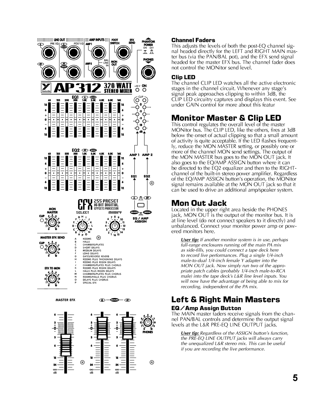
This adjusts the levels of both the
Clip LED
The channel CLIP LED watches all the active electronic stages in the channel circuit. Whenever any stage’s signal peak approaches clipping to within 3dB, the CLIP LED circuitry captures and displays this event. See under GAIN control for more about this featur
Monitor Master & Clip LED
This control regulates the overall level of the master MONitor bus. The CLIP LED, like the others, fires at 3dB below the onset of actual clipping so that a small amount of activity is quite acceptable. If the LED flashes frequent- ly, reduce the MON MASTER setting, or possibly one or more of the channel MON send settings. The output of the MON MASTER bus goes to the MON OUT jack. It also goes to the EQ/AMP ASSIGN button where it can be directed to the EQ2 equalizer and then to the RIGHT- channel of the
Mon Out Jack
Located in the upper right area beside the PHONES jack, MON OUT is the output of the monitor bus. It is at line level (do not connect speakers to it directly) and unbalanced. Connect your monitor power amp or pow- ered monitors here.
User tip: If another monitor system is in use, perhaps
to record live performances. Plug a single
Left & Right Main Masters
EQ/Amp Assign Button
The MAIN master faders receive signals from the chan- nel PAN/BAL controls and determine the output signal levels at the L&R
User tip: Regardless of the ASSIGN button’s function, the
5
