Instructions for the Installer
Engineers technical data |
| SUPPLY CONNECTIONS | |
OVERALL DIMENSIONS |
| Gas: | |
| RC 1/2 inch (1/2 inch male) Rear right hand corner | ||
Width: | 580 mm. | Electric: | |
Depth: | 510 mm. | ||
|
| ||
CUT OUT DIMENSIONS |
| APPLIANCE GAS SUPPLY: | |
Width: | 560 mm. | ||
Natural gas 1.0 kPa - Universal LPG 2.75 kPa | |||
Depth: | 480 mm. |
|
TYPE | TYPE | NOZZLE | NOMINAL | NOMINAL | |
OF BURNER | MARKS | GAS | PRESSURE | ||
OF GAS | |||||
| 1/100 mm | CONSUMPTION | kPa | ||
|
| ||||
|
|
| MJ/h |
| |
|
|
|
|
| |
NATURAL | Double Crown (wok) | 1.67 | 13.00 |
| |
1.11 | 6.80 | 1.00 | |||
GAS | Auxiliary (small) | 0.89 | 3.80 |
| |
|
| ||||
|
|
|
|
| |
| Double Crown (wok) | 1.02 | 13.00 |
| |
0.71 | 6.30 | 2.75 | |||
| Auxiliary (small) | 0.55 | 3.60 |
| |
|
|
|
|
|
Burner | Dia. Tap |
| 1/100 mm |
Auxiliary28
Double crown 42 Aeration adjustment none
Important safety requirements
Location
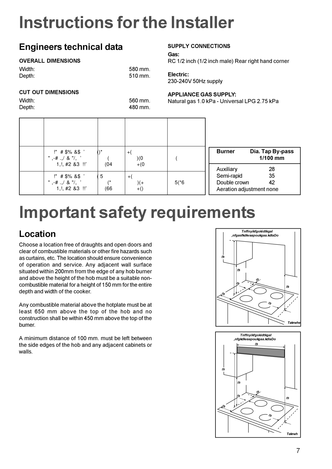
Choose a location free of draughts and open doors and clear of combustible materials or other fire hazards such as curtains, etc. The location should ensure convenience of operation and service. Any adjacent wall surface situated within 200mm from the edge of any hob burner and above the height of the hob must be a suitable non- combustible material for a height of 150 mm for the entire depth and width of the cooker.
Any combustible material above the hotplate must be at least 650 mm above the top of the hob and no construction shall be within 450 mm above the top of the burner.
A minimum distance of 100 mm. must be left between the side edges of the hob and any adjacent cabinets or walls.
|
| FITTING THE GAS HOB |
| |
| WITHOUT A COOKER HOOD ABOVE | |||
700 mm |
|
|
| |
| 400 mm |
|
| |
|
| mm |
|
|
| 50 | 55 |
|
|
| mm |
| 400 mm | |
|
|
| ||
|
|
|
| |
100 | mm |
|
|
|
|
|
|
| |
|
| 50 | mm |
|
|
|
|
| |
|
|
|
| FO 0812 |
|
| FITTING THE GAS HOB |
| |
| WITH A COOKER HOOD ABOVE |
| ||
|
| 600 mm |
|
|
650 mm |
|
|
| |
| 400 mm |
|
| |
|
| mm |
|
|
| 50 | 55 |
|
|
| mm |
| 400 mm | |
|
|
| ||
100 | mm |
|
|
|
|
|
|
| |
|
| 50 | mm |
|
|
|
|
| |
|
|
|
| FO 0813 |
|
|
|
| 7 |
