Manuals
/
Zanussi
/
Kitchen Appliance
/
Cooktop
Zanussi
ZGS 682 ICT
manual
Description of the Hobs
Models:
ZGS 682 I
ZGS 682 IC
ZGS 682 ICT
1
6
36
36
Download
36 pages
40.04 Kb
3
4
5
6
7
8
9
10
Install
Wiring diagram
Fault Finding
Warranty
Maintenance
Symptom Solution
Procedure
Safety
Service
Engineer technical data
Page 6
Image 6
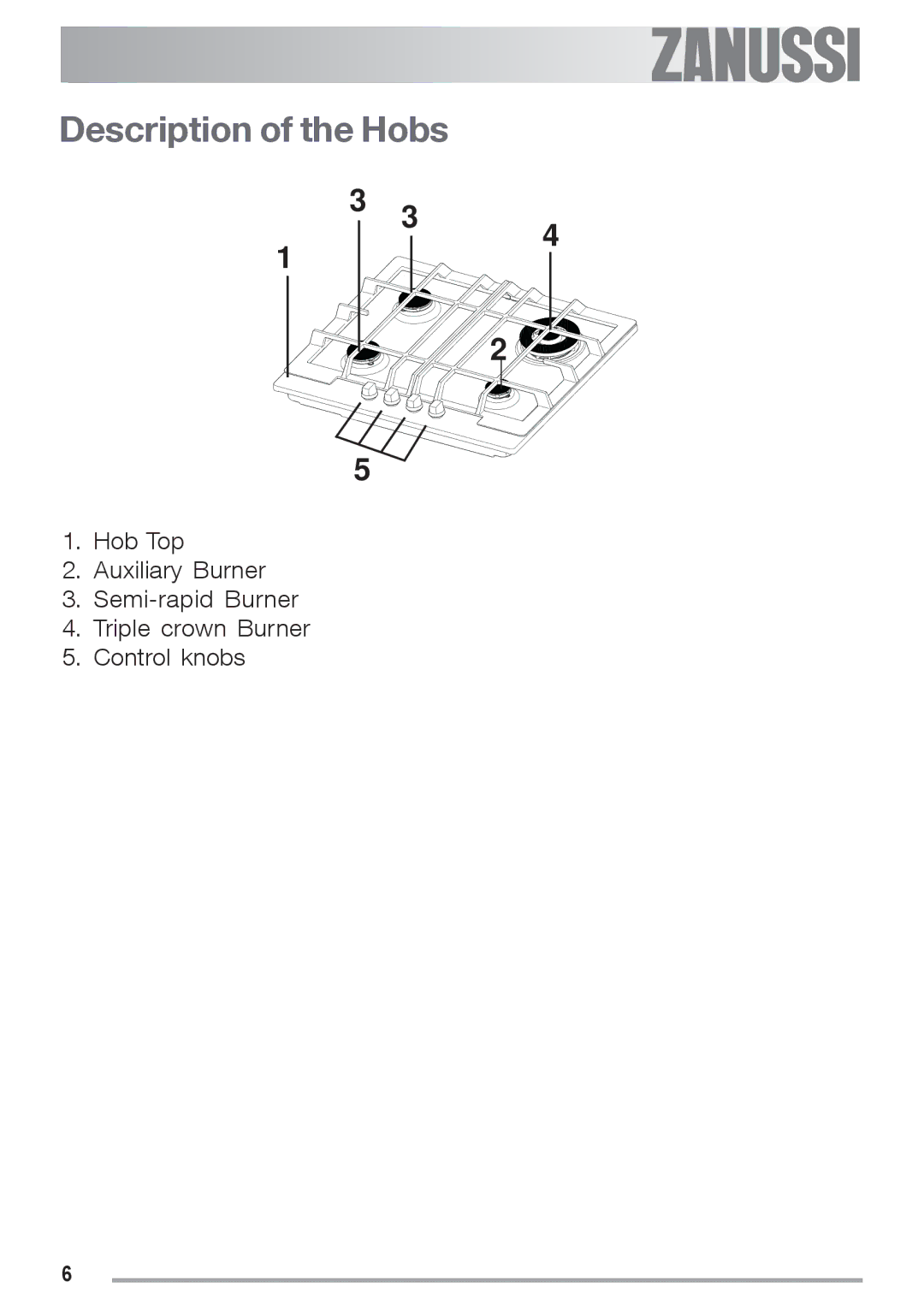
Description of the Hobs
3
3
1
4
2
5
1.
Hob Top
2.
Auxiliary Burner
3.
Semi-rapid
Burner
4.
Triple crown Burner
5.
Control knobs
6
Page 5
Page 7
Page 6
Image 6
Page 5
Page 7
Contents
GB IE
Thank you for selecting our appliance
Contents
People Safety
Important Safety Information
Installation
During Use
Service
Environmental Information
Description of the Hobs
Instructions for the User
Operation
Lighting
Using the hob correctly
Burner Minimum Maximum Diameter
Page
Maintenance and Cleaning
Hob Top
Pan Supports
Burners
Ignition electrode
Symptom Solution
Something Not Working?
Instructions for the Installer
Engineer technical data
Burner
Important safety requirements
Provision for Ventilation
Installation
Gas Connection
Location
Fitting the Hob into Worktop
Building
Building over a cupboard or drawer
Building over a kitchen unit with door
Electrical Connections
Electrical Requirements
Wiring diagram
Permanent Connection
Fault Finding
Preliminary Electrical Systems Check
Earth Continuity Check
Ignition System / Gas Ignition
Minimum adjustment
Pressure Testing
Procedure
Commissioning
Conversion from Natural Gas to LPG
Method
Guarantee/Customer Service
Exclusions
Service and Spare Parts
0870 5 929
European Guarantee
Page
Page
Page
Page
35699-4701 01/08 R.0
Top
Page
Image
Contents