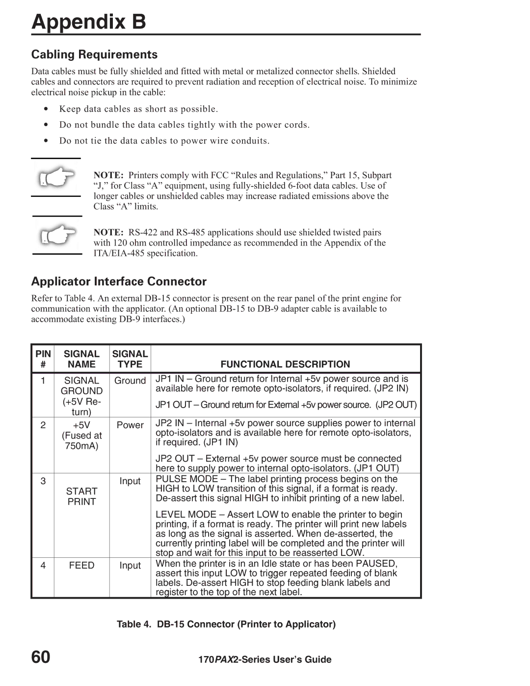
170PAX2TM specifications
Zebra Technologies, a leader in industrial printing solutions, offers the 170PAX2TM printer, a versatile and robust solution targeted towards high-performance applications. Designed for industrial environments, the 170PAX2TM stands out for its advanced features and technologies that elevate operational efficiency and streamline workflows.One of the key features of the 170PAX2TM is its exceptional printing speed. Capable of producing high-quality labels at a rapid pace, this printer significantly reduces the time required for label production, making it an ideal choice for businesses with large-scale printing needs. The printer supports a broad range of media types and sizes, allowing users to create everything from small labels to larger tags with ease.
Another hallmark of the 170PAX2TM is its rugged design. Built to endure the demanding conditions of industrial settings, this printer features a durable housing that can withstand impacts, dust, and moisture. This durability ensures long-term performance and reliability, reducing maintenance costs and downtime.
In addition to its robust build, the 170PAX2TM incorporates state-of-the-art printing technologies. It utilizes direct thermal and thermal transfer printing methods, providing flexibility for various label materials. The printer's advanced thermal printhead technology ensures sharp, clear images and text, which is essential for barcode clarity and scannability.
The 170PAX2TM also boasts user-friendly features, including a large LCD display that simplifies navigation and operation. With intuitive controls, users can easily adjust settings, monitor print jobs, and perform maintenance tasks with minimal training. The printer also supports various connectivity options, including USB, Serial, and Ethernet, making integration into existing systems straightforward.
The device is also designed with energy efficiency in mind. It features power-saving modes that help reduce energy consumption, contributing to a greener, more sustainable workplace. Additionally, its smaller footprint allows it to fit seamlessly into any production line without taking up excessive space.
Overall, Zebra Technologies' 170PAX2TM printer combines speed, durability, and advanced printing capabilities, making it an invaluable asset for businesses looking to enhance their labeling processes. Whether in warehousing, manufacturing, or distribution, the 170PAX2TM delivers dependable performance that meets the high demands of today's industrial environments.

