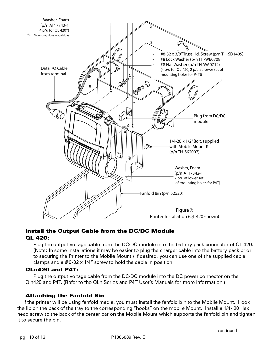
Qln420, QL420, RP4T, P4T specifications
Zebra Technologies is a leading provider of printing solutions, specializing in the design and manufacture of a wide range of printers and mobile devices. Among their impressive lineup are the QL420, RP4T, P4T, and QLn420 printers, each engineered to meet specific printing needs across various industries. These devices combine advanced technology with user-friendly features, making them essential tools for businesses looking to improve efficiency and productivity.The QL420 is a versatile, portable printer that excels in printing labels and receipts on-the-go. It features direct thermal printing technology, allowing for high-quality output without the need for ink or toner. This printer stands out with its robust construction, designed to withstand everyday use in challenging environments. The QL420 supports a variety of media sizes, making it ideal for applications in retail, logistics, and healthcare.
The RP4T is another outstanding model within Zebra's mobile printing range. This printer offers RFID capabilities, allowing users to print and encode RFID labels seamlessly. It is engineered for easy integration into existing workflows, with a simple interface and multiple connectivity options, including Bluetooth and Wi-Fi. The RP4T's lightweight design and long-lasting battery enhance portability, making it perfect for field operations where mobility is essential.
The P4T printer also focuses on providing RFID printing solutions but enhances this experience by offering rugged durability. It features a robust design that meets military standards for durability and environmental resistance. The P4T is capable of printing on a wide range of materials, making it suitable for harsh conditions, including outdoor and industrial applications. Its versatile connectivity options ensure compatibility with various devices and networks.
Lastly, the QLn420 represents the pinnacle of Zebra's mobile printing technology. This model is designed with user comfort in mind, offering an ergonomic design that minimizes user fatigue during extended use. The QLn420 provides high-resolution printing, ensuring clear and detailed labels and receipts. With advanced management features and a user-friendly interface, it provides users with everything they need to streamline operations efficiently.
In summary, Zebra Technologies offers a diverse range of portable printers – the QL420, RP4T, P4T, and QLn420 – each equipped with unique features and capabilities that cater to different printing needs. With their emphasis on durability, connectivity, and user-friendliness, these printers are invaluable assets for businesses across various sectors, enhancing operational efficiency and productivity.

