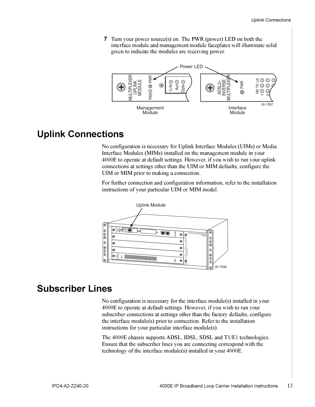
4000E specifications
Zhone Technologies has long been recognized as a leader in providing innovative and advanced networking solutions for telecommunications and internet service providers. Among its notable offerings, the Zhone 4000E series stands out as a versatile and robust platform designed to meet the demands of modern network environments. This article explores the main features, technologies, and characteristics of the Zhone 4000E.One of the key features of the Zhone 4000E is its flexibility in deployment. This platform supports a range of access technologies, including xDSL, fiber, and Ethernet, making it suitable for various use cases, whether in urban or rural settings. The ability to support multiple access methods allows service providers to deliver high-speed internet and voice services to diverse customer demographics without the need for extensive hardware or infrastructure changes.
The Zhone 4000E is powered by a highly scalable architecture, enabling service providers to easily expand their network capacity as demand grows. This scalability is critical in an era where internet usage is continually increasing. Its modular design allows operators to add or upgrade components seamlessly, ensuring that their network can adapt to emerging technologies and growing traffic requirements.
In terms of performance, the Zhone 4000E excels with its advanced Quality of Service (QoS) capabilities. This feature prioritizes network traffic to ensure that real-time services such as voice over IP (VoIP) and video streaming receive the necessary bandwidth and low latency to function optimally. This capability is increasingly important as consumer expectations for service quality are higher than ever.
Another significant aspect of the Zhone 4000E is its robust security features. With built-in encryption and advanced firewalls, the platform ensures that both service providers and end-users can operate their networks with confidence. Security is a crucial concern in today’s digital landscape, and Zhone has made addressing this a priority in their product design.
Furthermore, the Zhone 4000E is equipped with comprehensive management tools that simplify network monitoring and troubleshooting. These tools provide real-time insights into network performance and can help identify potential issues before they affect customers. This proactive approach to management helps service providers maintain high levels of customer satisfaction and operational efficiency.
In summary, the Zhone 4000E series is a highly versatile and capable platform that combines flexibility, scalability, performance, security, and management efficiency. Its ability to adapt to various technologies and growing demands makes it an excellent choice for service providers looking to enhance their offerings and stay competitive in a fast-evolving digital market.

