Intel GA-8I915MK-GV user manual FUSB1 / FUSB2 Front USB Connectors, Comb Comb Connector

Page 25

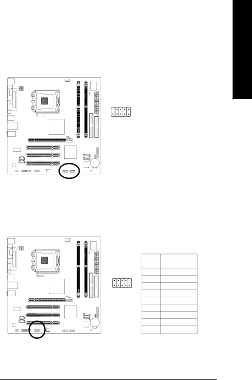
15)F_USB1 / F_USB2 (Front USB Connectors)

Be careful with the polarity of the front USB connector. Check the pin assignment carefully while you connect the front USB cable, incorrect connection between the cable and connector will make the device unable to work or even damage it. For optional front USB cable, please contact your local dealer.


Pin No.

Definition


1

Power

9

2

2

Power

3

USB0 DX-


1

4

USB1 Dy-

10

5

USB0 DX+


6

USB1 Dy+


7

GND


8

GND


9

No Pin


10

NC


16)COMB (COMB Connector)

Be careful with the polarity of the COMB connector. Check the pin assignments while you connect the COMB cable. Please contact your nearest dealer for optional COMB cable.


Pin No.

Definition


1

NDCDB-

2

10

2

NSINB

3

NSOUTB


1

9

4

NDTRB-

5

GND


6

NDSRB-


7

NRTSB-


8

NCTSB-


9

NRIB-


10

No Pin

English

- 25 -

Hardware Installation

Image 25
Contents GA-8I915MK-GV Motherboard Product Manual Classification CopyrightTable of Contents Install Drivers 8I915MK-GV GA-8I915MK-GV Motherboard LayoutBlock Diagram Page Installation Notices Considerations Prior to InstallationInstances of Non-Warranty Preparing Your ComputerCPU Feature SummaryUse of licensed Award Bios Installation of the CPU Installation of the CPU and HeatsinkInstallation of the Heatsink Installation of Memory Dual Channel DDR Installation of Expansion CardsI/O Back Panel Introduction English Connectors IntroductionATX12V/ATX Power Connector FDD FDD Connector Cpufan / Sysfan Cooler Fan Power ConnectorSATA0/SATA1 Serial ATA Connector IDE1 IDE ConnectorFpanel Front Panel Connector Pwrled Faudio Front Audio Panel ConnectorAuxin AUX In Connector Cdin CD in ConnectorSurcen Spdifio Spdif In/ OutComb Comb Connector FUSB1 / FUSB2 Front USB ConnectorsClrcmos Clear Cmos CI Chassis Intrusion, Case OpenBAT Battery English Main Menu Status Page Setup Menu / Option Page Setup MenuMain Menu For example Bios Ver. F1 Standard Cmos Features IDE Channel 0 Master, Slave Floppy 3 Mode Support for Japan AreaIDE Channel 2/3 Master, Slave Drive a / Drive BMemory Halt onBase Memory Extended MemoryHard Disk Boot Priority Advanced Bios FeaturesFirst / Second / Third Boot Device CPU Hyper-Threading Password CheckLimit Cpuid Max. to No-Execute Memory Protect NoteSPP Integrated PeripheralsUSB 2.0 Controller Onboard LAN Boot ROMUSB Keyboard Support USB Mouse SupportParallel Port Mode Power Management SetupECP Mode Use DMA Resume by Alarm Power On by RingPower On By Mouse Power On By KeyboardPCI 1 IRQ Assignment PnP/PCI ConfigurationsPC Health Status Frequency / Voltage Control CPU Smart FAN ModeCPU Smart FAN Control CPU Clock RatioCPU Host Frequency Mhz CPU Host Clock ControlPCI-E Frequency to CPU Memory Frequency ForCPU Voltage Control FSB OverVoltage ControlNormal CPU Vcore Load Optimized Defaults Load Fail-Safe DefaultsSet Supervisor/User Password Exit Without Saving Save & Exit SetupEnglish Install Chipset Drivers Install DriversDriver CD Information Software ApplicationsContact Us Hardware InformationEnglish Unique Software Utilities User Interface Overview EasyTune 5 IntroductionWhat is Xpress Recovery ? Xpress Recovery IntroductionHow to use the Xpress Recovery F9 For Xpress Recovery Exit and Restart Remove Backup Image  Remove backup image. Are you sure? Y/NMethod 1 Q-FlashTMUtility Flash Bios Method IntroductionBefore You Begin Task menu for Dual Bios utility Exploring the Q-FlashTM / Dual Bios utility screenEntering the Q-FlashTMutility Task menu for Q-Flash utilitySteps Using the Q-FlashTMutilityYou can repeat to Part Two FlashTMutility bar Exploring the Q-FlashTMutility screenCongratulation!! You have updated Bios successfully Methods and steps Method 2 @BIOSTM UtilityEnglish 5 2 / 4 / 6 Channel Audio Function Introduction Channel Audio SetupChannel Analog Audio Output Mode Basic 6 Channel Analog Audio Output Mode English Basic 6 Channel Analog Audio Output Mode Notes Spdif Output Device Optional Device AMI Bios Beep Codes TroubleshootingEnglish English English English English Taiwan Headquarters Contact UsChina Shanghai