Extron electronic SW DVI A Series user manual Three, Operation

Page 14

Installation, cont’d

To enable autoswitching,

1. Cut a small piece of wire to use as a jumper.

2. Insert the ends of the wire into pin holes 4 and 5 of the provided 5-pole captive screw plug, connecting pins 4 and 5 together. (See the figure at right.)

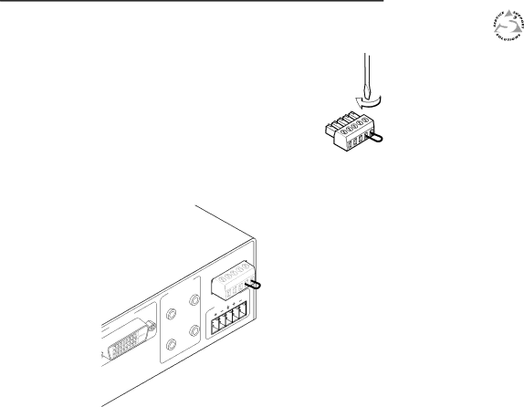
3. Use an Extron Tweeker or other small screwdriver to tighten the plug’s two screws above pin slots 4 and 5, so that the jumper wire ends remain securely in place.

4. Insert the plug into the 5-pole captive screw connector on the SW2/SW4 rear panel.

-

SW

/


S

INPU

T

3

1

OUTPU

2


T

1


OUTPU

4


2

Remote/Auto-Sw connector with pins 4 and 5 connected by a jumper

Autoswitching remains in effect as long as the jumper wires are connecting the two pins together.

SW DVI A Series

Chapter3Three

Operation

Front Panel Features

Operations

Updating Firmware

2-14 SW DVI A Series • Installation

Image 14
Contents DVI and Audio Switchers User’s ManualPrecautions Extron’s Warranty安全须知 中文 FCC Class a NoticeTable of Contents SW DVI a Series Table of Contents, cont’dIntroduction About this Manual FeaturesIntroduction About the SW DVI a SeriesExtron InstallationIntroduction, cont’d Application Diagram Mounting the SW DVI a Series InstallationInstallation Overview Tabletop useInstallation, cont’d Back of the rack mountingFurniture mounting Preparing the SW2/SW4 for under-desk mounting Installation, cont’d Rear Panel Features SW2 DVI a rear panelAudio Connectors Installation, cont’d Wiring the Power ConnectorDVI-I Video Connectors Pin SignalEnabling autoswitching Wiring the Remote/Autoswitching ConnectorWiring for RS-232 Audio outputThree OperationOperation Front Panel FeaturesPowering on the switcher OperationsEnabling front panel lockout executive mode Using the IR 102 remote controlLocking IR remote access Remote control buttonsUpdating Firmware Setting equalization for input sourcesResetting Downloading the firmwareLoading the firmware to the switcher On the first screen that appears, select the RS-232 tabSIS Configuration and Control FourUsing the Command/Response Table SIS Configuration and ControlHost-to-Switcher Communications Command/response table for SIS commands Input selectionSpecifications, Part Numbers Accessories SIS Configuration and Control, cont’dSpecifications, Part Numbers, Accessories SpecificationsIncluded Parts Specifications, Part Numbers, Accessories, cont’dAccessories Cables Part numbers