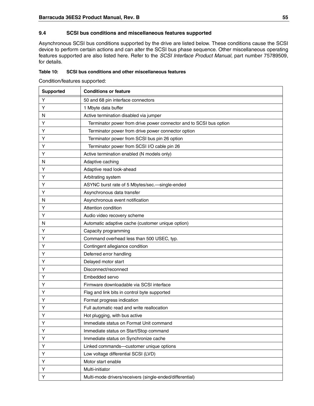
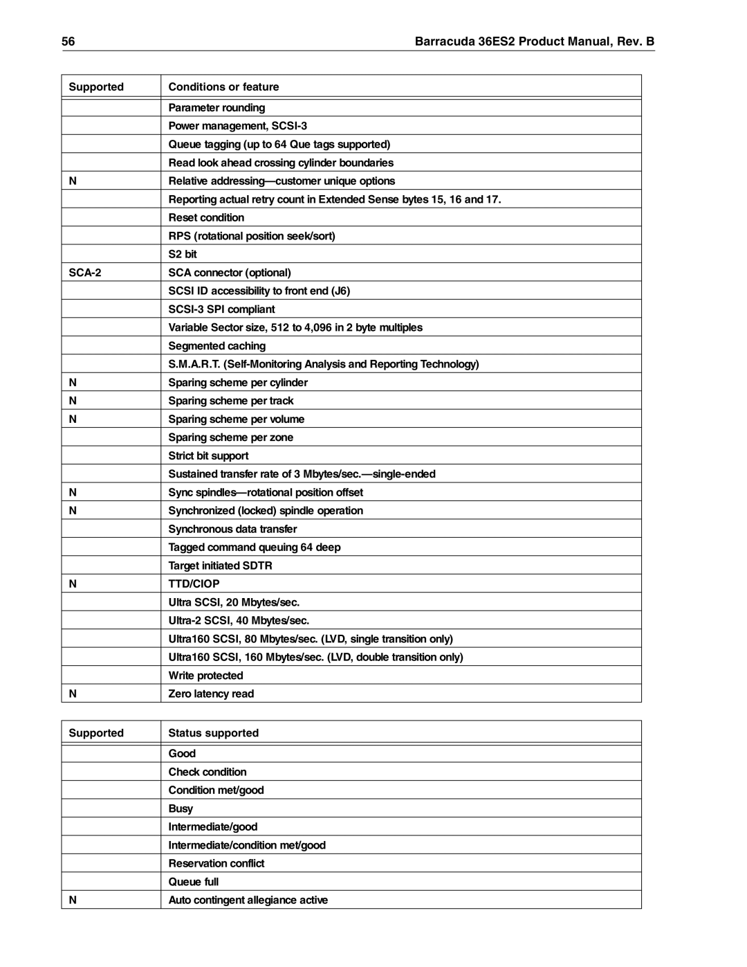
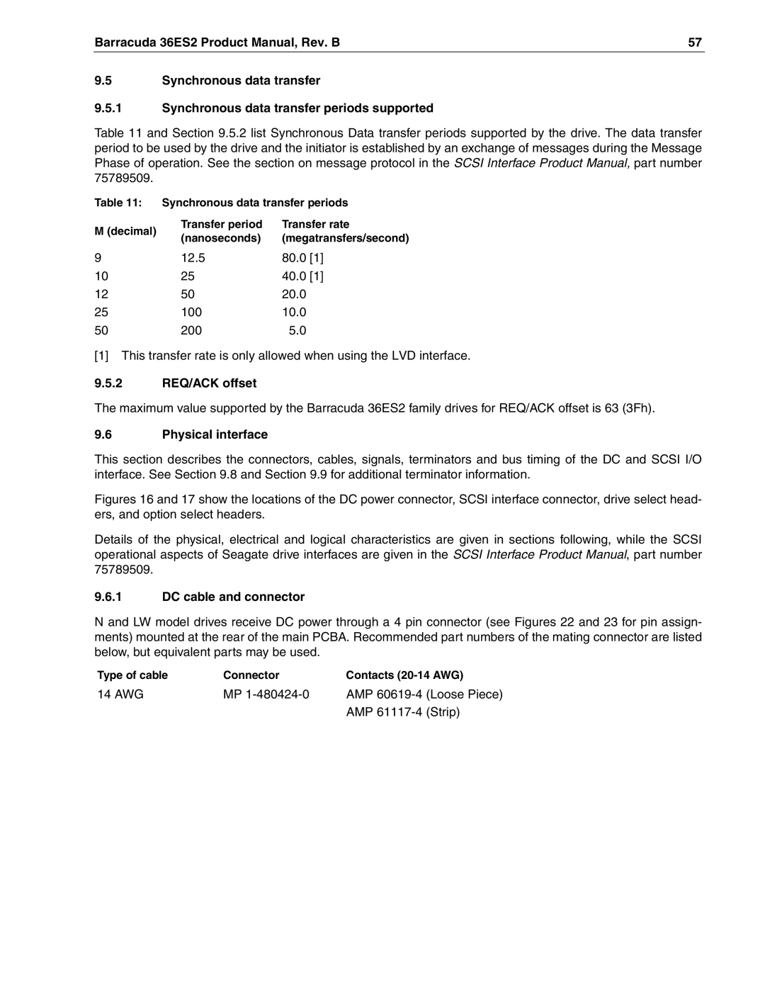
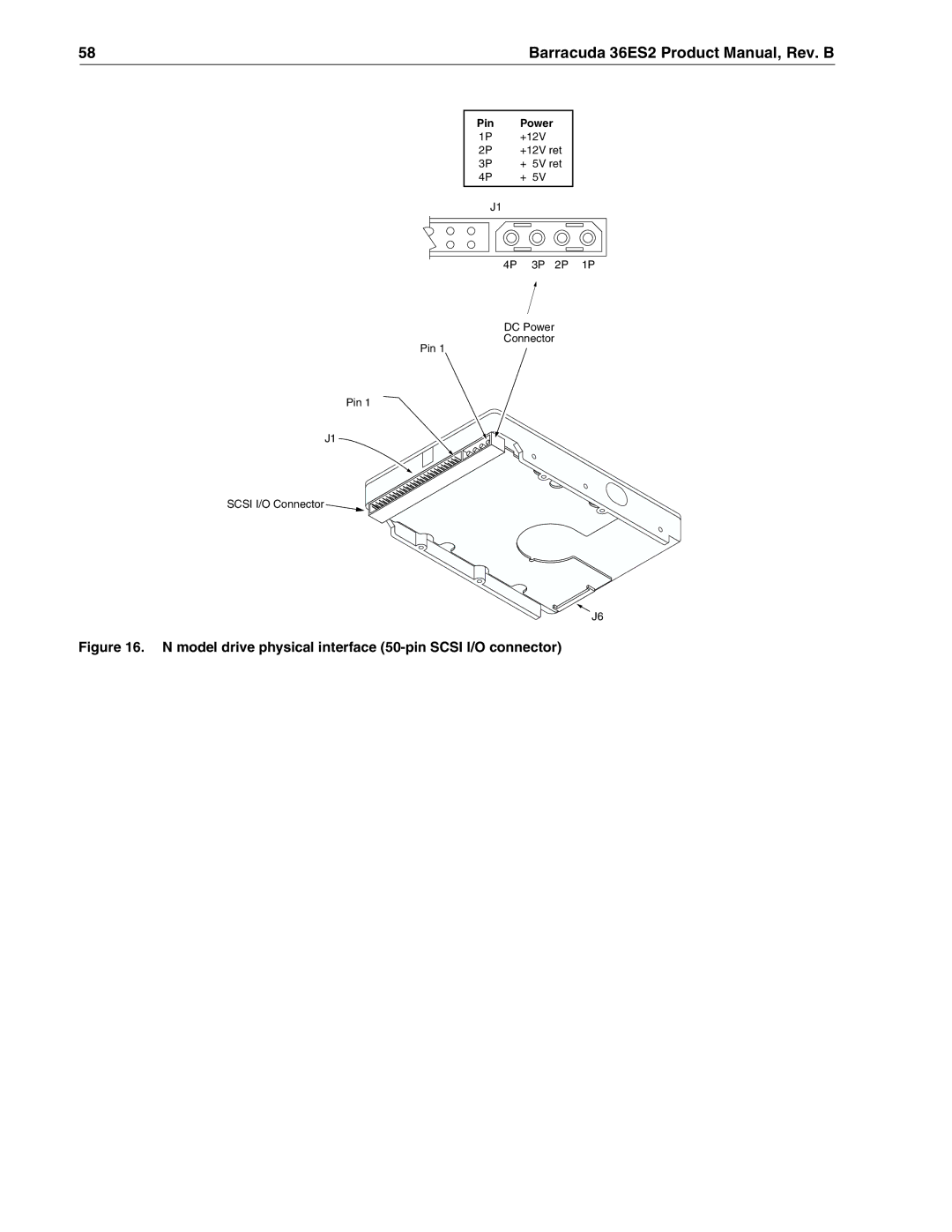
Seagate ST336938LW, ST318418N, ST318438LW, ST336918N manual Mode Sense data

Page 62

52

Barracuda 36ES2 Product Manual, Rev. B

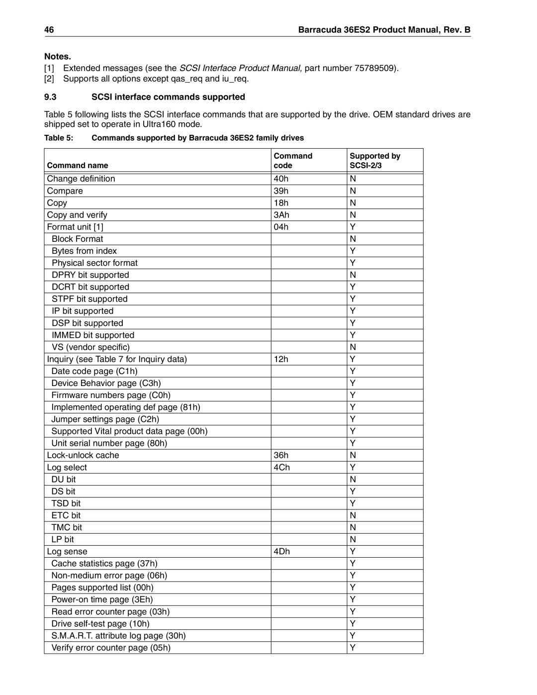
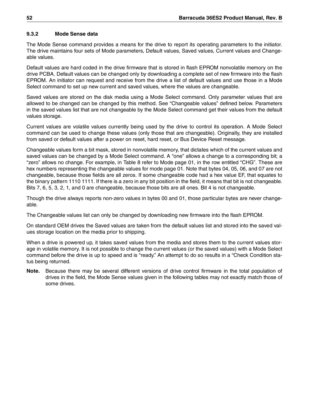
9.3.2Mode Sense data

The Mode Sense command provides a means for the drive to report its operating parameters to the initiator. The drive maintains four sets of Mode parameters, Default values, Saved values, Current values and Change- able values.

Default values are hard coded in the drive firmware that is stored in flash EPROM nonvolatile memory on the drive PCBA. Default values can be changed only by downloading a complete set of new firmware into the flash EPROM. An initiator can request and receive from the drive a list of default values and use those in a Mode Select command to set up new current and saved values, where the values are changeable.

Saved values are stored on the disk media using a Mode Select command. Only parameter values that are allowed to be changed can be changed by this method. See “Changeable values” defined below. Parameters in the saved values list that are not changeable by the Mode Select command get their values from the default values storage.

Current values are volatile values currently being used by the drive to control its operation. A Mode Select command can be used to change these values (only those that are changeable). Originally, they are installed from saved or default values after a power on reset, hard reset, or Bus Device Reset message.

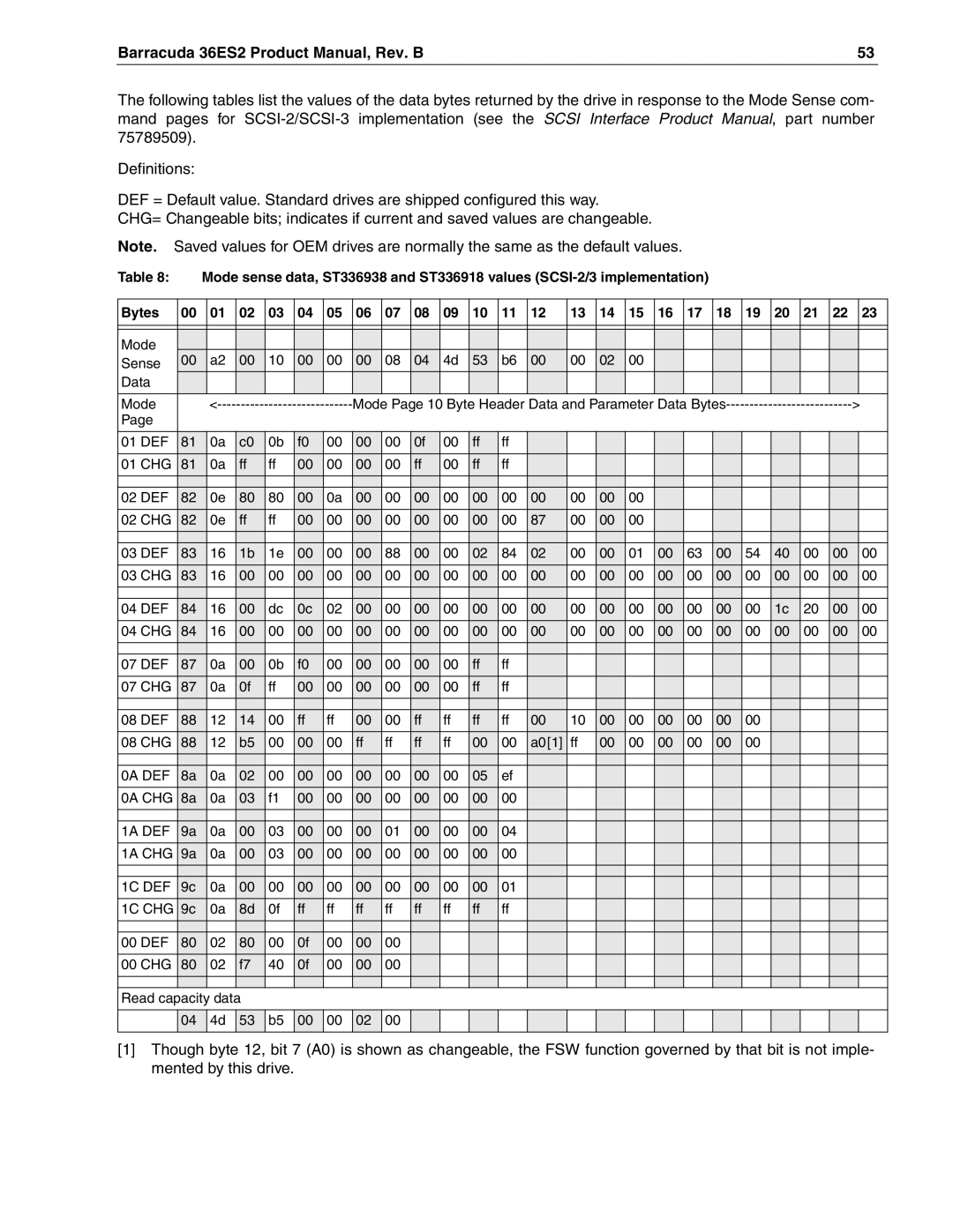
Changeable values form a bit mask, stored in nonvolatile memory, that dictates which of the current values and saved values can be changed by a Mode Select command. A “one” allows a change to a corresponding bit; a “zero” allows no change. For example, in Table 8 refer to Mode page 01, in the row entitled “CHG”. These are hex numbers representing the changeable values for mode page 01. Note that bytes 04, 05, 06, and 07 are not changeable, because those fields are all zeros. If some changeable code had a hex value EF, that equates to the binary pattern 1110 1111. If there is a zero in any bit position in the field, it means that bit is not changeable. Bits 7, 6, 5, 3, 2, 1, and 0 are changeable, because those bits are all ones. Bit 4 is not changeable.

Though the drive always reports non-zero values in bytes 00 and 01, those particular bytes are never change- able.

The Changeable values list can only be changed by downloading new firmware into the flash EPROM.

On standard OEM drives the Saved values are taken from the default values list and stored into the saved val- ues storage location on the media prior to shipping.

When a drive is powered up, it takes saved values from the media and stores them to the current values stor- age in volatile memory. It is not possible to change the current values (or the saved values) with a Mode Select command before the drive is up to speed and is “ready.” An attempt to do so results in a “Check Condition sta- tus being returned.

Note. Because there may be several different versions of drive control firmware in the total population of drives in the field, the Mode Sense values given in the following tables may not exactly match those of some drives.

Image 62
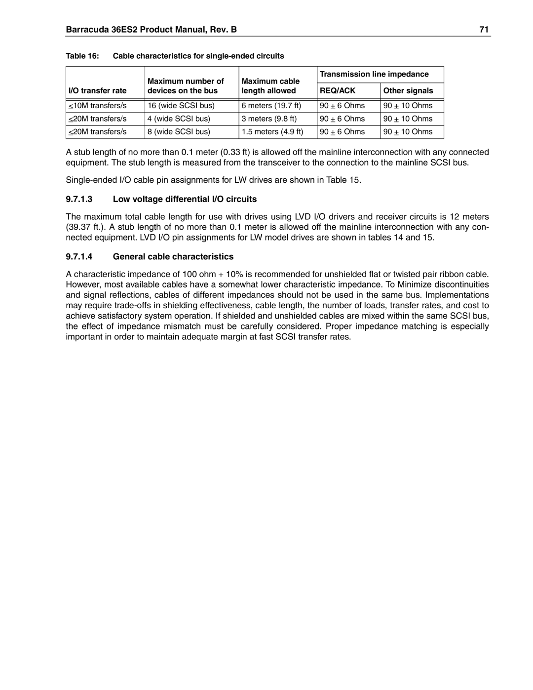
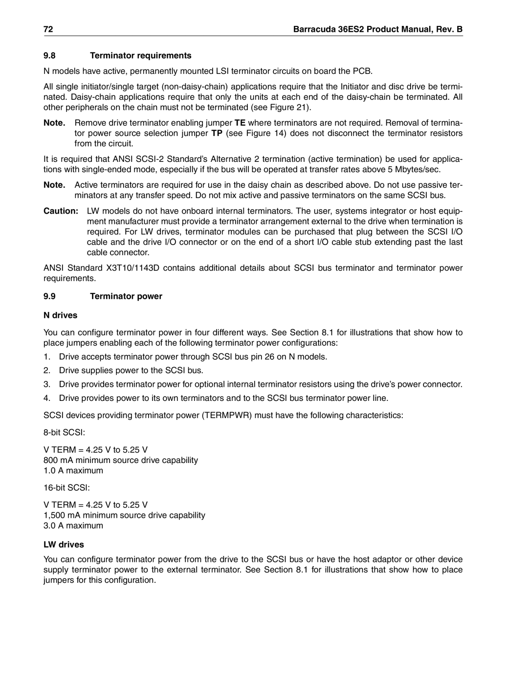
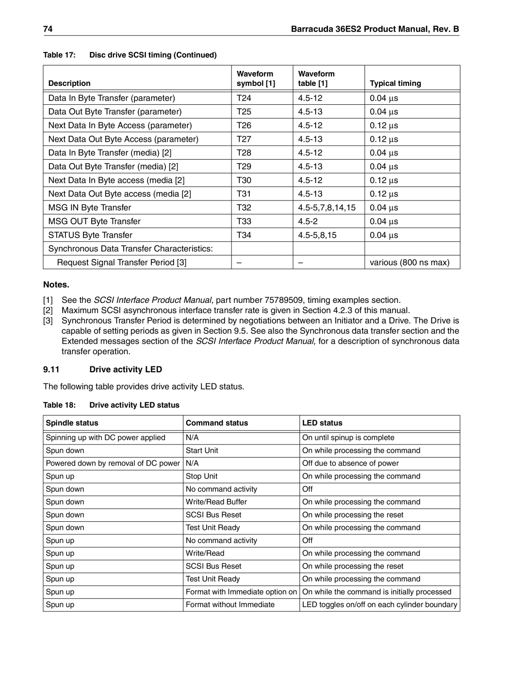
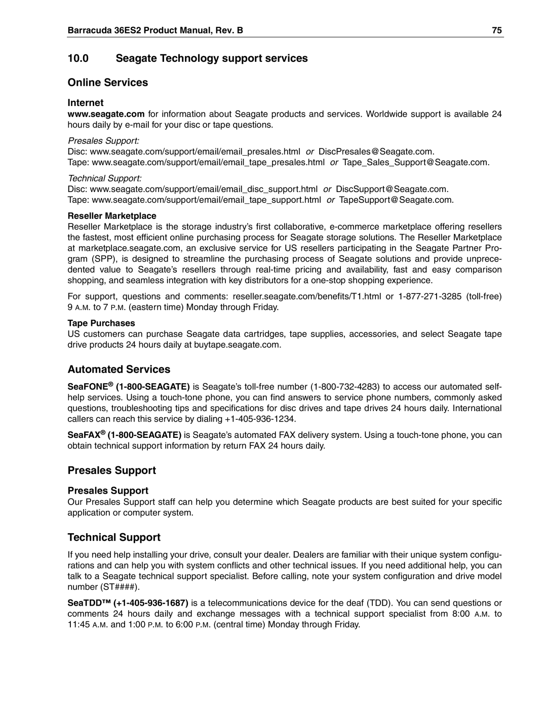
Contents Product Manual, Volume Page Product Manual, Volume Page Revision status summary sheet Revision Date Writer/Engineer Sheets AffectedPage Contents Seagate Technology support services Defect and error managementInstallation Interface requirementsList of Figures Barracuda 36ES2 Product Manual, Rev. B ViiPage Scope Barracuda 36ES2 family drive ST336938LW shownBarracuda 36ES2 Product Manual, Rev. B Applicable standards and reference documentation Taiwanese Bsmi Australian C-TickKorean MIC General description Performance Standard featuresMedia characteristics ReliabilityProgrammable drive capacity Factory installed accessoriesOptions factory installed Performance characteristics Prefetch/multi-segmented cache control Ultra2 Scsi Ultra160 ScsiStart/stop time Cache operation Caching write dataPrefetch operation Barracuda 36ES2 Product Manual, Rev. B Reliability specifications Service life Reliability and servicePreventive maintenance Service philosophy7 S.M.A.R.T Controlling S.M.A.R.TDetermining rate Performance impactReporting control Predictive failuresImplementation State of the drive prior to testingDST Failure Definition Invoking DSTExtended test Function Code 010b Product warrantyShort test Function Code 001b Log page entriesProduct repair and return information Barracuda 36ES2 Product Manual, Rev. B DC power requirements Physical/electrical specificationsAC power requirements 3 12 V Current profile Power sequencingConducted noise immunity +5 Volt Current during spindle start Typical Amper es Amps Power dissipation ST336938/ST318438 Barracuda 36ES2 Product Manual, Rev. B ST336918/ST318418 Temperature Environmental limitsShock and vibration Barracuda 36ES2 Product Manual, Rev. B Relative humidityEffective altitude sea level ShockRecommended mounting Acoustics Air cleanlinessBarracuda 36ES2 Product Manual, Rev. B Vibration Mechanical specifications Dimension TableMounting configuration dimensions Barracuda 36ES2 Product Manual, Rev. B Drive internal defects Defect and error managementDrive error recovery procedures Scsi systems errors Formatting InstallationConfigure drive options Drive ID/option select headerDo not install jumpers retain cover J6 jumper header for N model J5 jumper header on LW models only J2 option select header for LW models Barracuda 36ES2 Product Manual, Rev. B Barracuda 36ES2 Product Manual, Rev. B Function description Air flow Drive orientationCooling Barracuda 36ES2 Product Manual, Rev. B Drive mounting GroundingBarracuda 36ES2 Product Manual, Rev. B Interface requirements Scsi interface messages supportedScsi interface commands supported Commands supported by Barracuda 36ES2 family drives Barracuda 36ES2 Product Manual, Rev. B Vendor ID Implemented operating definition page 81h Inquiry Vital Product dataUnit serial number page 80h Firmware numbers page C0hJumper settings page C2h Mode Sense data DEF CHG Barracuda 36ES2 Product Manual, Rev. B Condition/features supported Supported Status supported Physical interface DC cable and connector2 REQ/ACK offset Model drive physical interface 50-pin Scsi I/O connector Pin Power Scsi interface physical description Scsi interface cable requirementsBarracuda 36ES2 Product Manual, Rev. B Mating connectors Mating connectors for N model drivesScsi daisy chain interface cabling for N drives Nonshielded 68 pin Scsi device connector used on LW drives Scsi daisy chain interface cabling for LW drives GND GND DBP1 +DBP1 Multimode-SE and LVD alternatives Multimode signalsElectrical description Input characteristics LVD output signalsSingle-ended drivers/receivers for N models Transmitter characteristicsReceiver characteristics Single-ended drivers/receivers for LW modelsGeneral cable characteristics Low voltage differential I/O circuitsLW drives Terminator power DrivesTerminator requirements Page Drive activity LED Following table provides drive activity LED statusPresales Support Seagate Technology support services Online ServicesAutomated Services Technical SupportEuropean Support Services Customer Service CSOUSA/Canada/Latin America Support Services Call Center Toll-free Direct dial Africa/Middle East Support ServicesAsia/Pacific Support Services Barracuda 36ES2 Product Manual, Rev. B Index Diffsens LED PCB System chassis Barracuda 36ES2 Product Manual, Rev. B