|
|
|
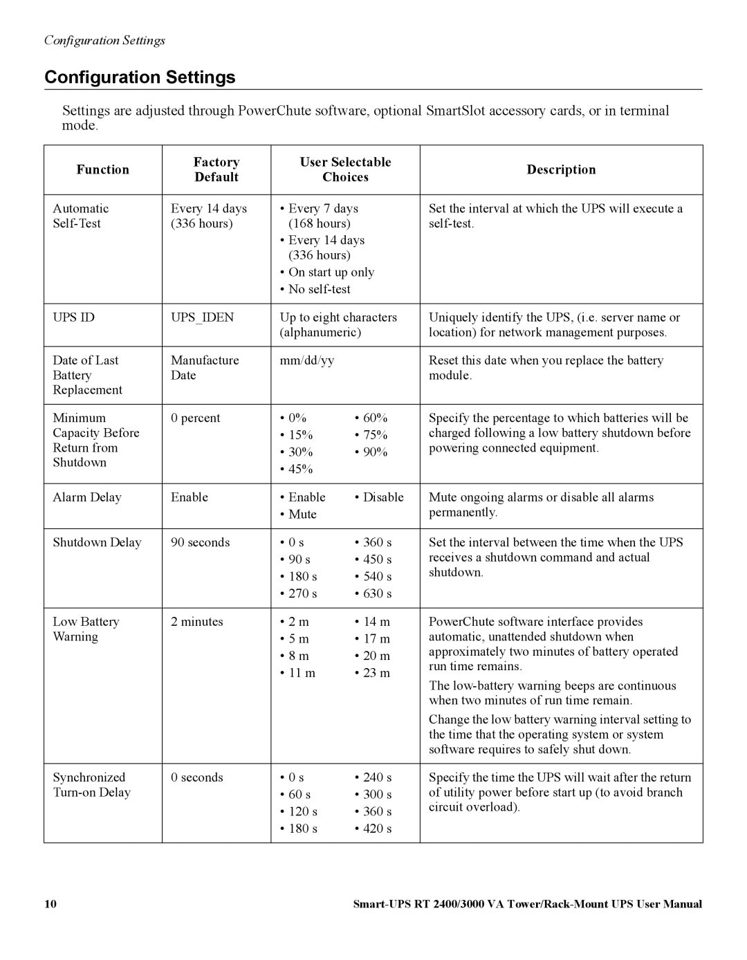
| Configuration Settings | |
|
|
|
| ||
Function | Factory | User Selectable | Description | ||
Default | Choices | ||||
|
| ||||
|
|
|
|
| |
High Bypass | 100V Models: | 100V | Maximum voltage that the UPS will pass to | ||
Points | 110V | • 107V | • 127V | connected equipment during internal bypass | |
| 120V Models: | • 110V | • 130V | operation. | |
| 133V | • 113V | • 133V |
| |
|
| • 116V | • 136V |
| |
|
| • 119V | • 139V |
| |
|
| • 122V | • 142V |
| |
|
| • 125V | • 145V |
| |
|
| • 128V | • 148V |
| |
|
|
|
|
| |
Low Bypass | 100V Models: | 100V | Minimum voltage that the UPS will pass to | ||
Points | 78V | • 78V | • 86V | connected equipment during internal bypass | |
| 120V Models: | • 80V | • 88V | operation. | |
| 86V | • 82V | • 90V |
| |
|
| • 84V | • 92V |
| |
|
| • 86V | • 94V |
| |
|
| • 88V | • 96V |
| |
|
| • 90V | • 98V |
| |
|
| • 92V | • 100V |
| |
|
|
|
|
| |
Output Frequency | Automatic | Automatic |
| Sets the allowable UPS output frequency. | |
| 50 ± 3 Hz or | 50 ± 3 Hz or |
| Whenever possible, the output frequency tracks | |
| 60 ± 3 Hz | 50 ± 0.1 Hz |
| the input frequency. | |
|
|
| |||
|
| 60 ± 3 Hz or |
|
| |
|
| 60 ± 0.1 Hz |
|
| |
|
|
|
| ||
Number of Battery | 1 | Number of connected | Defines the number of connected battery packs | ||
Packs |
| battery packs |
| for proper run time prediction. | |
|
|
|
| 1 = internal battery module, | |
|
|
|
| 2 = one SURT192XLBP or SURT192XLBPJ, 3 = | |
|
|
|
| two SURT192XLBP or SURT192XLBPJ, etc. | |
|
|
|
|
| |
11 |
