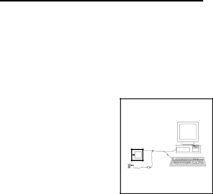
Connection of a MS860i-17 Scanner to a PC
To maintain compliance with applicable standards, all circuits connected to the scanner must meet the requirements for SELV (Safety Extra Low Voltage) according to EN 60950.
1.Attach the adaptor to the communication cable if needed.
2.If the PC is on, exit your application and turn the PC off.
3.Disconnect the keyboard from the PC. Plug the communication cable to the PC and the keyboard. Connect the
4.Check the AC input requirements of the transformer to make sure the voltage matches the AC outlet. (A socket outlet shall be installed near the equipment and shall be easily accessible.)
5. Plug the transformer into the side of the female
Figure 1
Note: Once the scanner is connected to the PC, the PC can be turned on and will operate normally even if the scanner’s transformer is not plugged in. However, bar codes will not be read until power is applied to the scanner.
When the scanner first receives power, the LEDs will flash and the scanner will beep once. After the scanner performs this start up sequence, the green LED will remain on for a specified time indicating the laser is on.
For information concerning keyboard wedge features, refer to the section, Version 17 Keyboard Wedge Scanner.
10