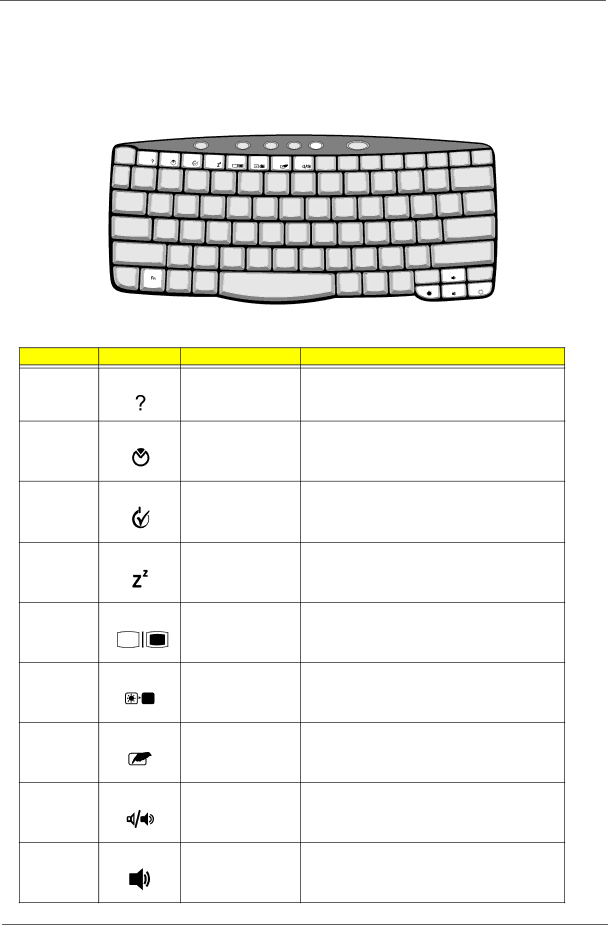
Acer C300 Series manual Hot Keys, Icon Function Description

Page 25

Hot Keys

The computer uses hotkey or key combinations to access most of the computer’s controls like sreen brightness, volume output.

To activate hot keys, press and hold the Fn key before pressing the other key in the hot key combination.

Hot Key

Icon

Function

Description

Fn-F1


Hot key help

Displays help on hot keys.

Fn-F2


System Property

Displays the System Property.

Fn-F3


Power Options

Display the Power Options Properties used by the


computer (function available if supported by operating


system).


See “Power management” on page 25.

Fn-F4


Sleep

Puts the computer in Sleep mode.


See “Power management” on page 25.

Fn-F5


Display toggle

Switches display output between the display screen,


external monitor (if connected) and both the display


screen and external monitor.

Fn-F6


Screen blank

Turns the display screen backlight off to save power.


Press any key to return.

Fn-F7


Touchpad toggle

Turns the internal touchpad on and off.

Fn-F8


Speaker toggle

Turns the speakers on and off.

Fn-w


Volume up

Increases the speaker volume.

Chapter 1

17

Image 25
Contents Acer TravelMate C300 Series Revision History Date Chapter UpdatesDisclaimer CopyrightScreen Messages ConventionsPreface Page Table of Contents Viii Chapter FeaturesExpansion Canary Block Top View Board LayoutSW2 Bottom View Front View Outlook ViewIcon Description Chapter Left view Right view Rear Panel Bottom Panel Icon Function Description IndicatorsChapter Lock Key Description Lock KeysEmbedded Numeric Keypad Desired Access Num Lock On Num Lock OffKey Icon Description Windows KeysHot Keys Icon Function Euro Symbol Launch Keys Launch Key Default applicationTouchpad Basics TouchpadFunction Left Button Right Button Scroll Button Tap Function Left Button Right Button Scroll Button Tap Specification Hardware Specifications and ConfigurationsProcessor Second Level CacheWireless Module 802.11b Bluetooth-MODEM InterfaceMemory Combinations Modem InterfaceHard Disk Drive Interface Four-in-One Card ReaderDVD-RW Interface DVD/CDRW InterfaceSpeaker DVD InterfaceVideo Interface Audio InterfaceVideo Memory Video Resolutions Mode for both LCD and CRTParallel Port Ieee 1394 Port USB PortPcmcia Port System Board Major ChipsSimultaneously by software specification BatteryKeyboard LCD Inverter System Power ManagementAC Adaptor Memory Address MapInterrupt Channel IRQ Assignment MapDMA Channel Assignment Chapter System Utilities Bios Setup UtilityNavigating the Bios Utility Parameter InformationMain Advanced Security Boot ExitParameter Description Format/Option Option Enabled or DisabledEsc Exit AdvancedClear or Set SecurityParameter Description Option Setting a Password Page CD-ROM Drive BootParameter Description ExitBios Flash Utility Machine Disassembly and Replacement Before You Begin General InformationMDC Disassembly Procedure FlowchartRemoving the Battery Pack Removing the Optical Disc Drive Module Removing the LCD Module Page Disassembling the Main Unit Disassembling the logic upper assemblyDisassembling the logic lower assembly Chapter Disassembling the LCD Module Chapter Chapter Disassembling and Reassembling the HDD Module Disassembling the External ModulesPage Assemble the Hinge Caps Symptoms Verified Go To TroubleshootingExternal Diskette Drive Check System Check ProceduresExternal CD-ROM Drive Check Keyboard or Auxiliary Input Device CheckMemory check Power System CheckTouchpad check Check the Battery PackPower-On Self-Test Post Error Message Error Message List Index of Error MessagesError Messages FRU/Action in Sequence LCD No beep Error Messages FRU/Action in SequenceCode Beeps Post Routine Description Post CodesChapter Code Beeps Post Routine Description Code Beeps For Boot Block in Flash ROM LCD-Related Symptoms Index of Symptom-to-FRU Error MessageIndicator-Related Symptoms Power-Related SymptomsMemory-Related Symptoms PCMCIA-Related SymptomsSpeaker-Related Symptoms Power Management-Related SymptomsKeyboard/Touchpad-Related Symptoms Peripheral-Related SymptomsModem/LAN-Related Symptoms Intermittent Problems Dimm Undetermined ProblemsChapter Top View SW2-1 SW2-2 Bottom ViewFRU Field Replaceable Unit List Battery Pack LI-ION 8CELL Sanyo BTP Exploded DiagramRTC Battery Adapter 19V 70W 3PIN Delta ADP-65DBWireless LAN Board 802.11B Intel MODEM/BLUETOOTH Board AmbitPower Cord 10A 125V Kingcord US Extension BoardMini PCI Cover W/SCREW Pack Lower Case Left Cover Power SwitchLower Case Front Cover W/SPEAKER Side Lower Case Right Cover Smart CardWireless LAN Antenna AUX Bluetooth AntennaWireless LAN Antenna Main Card Reader Bracket AssemblyHDD Drive 20G Hgst IC25N020ATMR04 HDD Drive 60G Hgst IC25N060ATMR04HDD Drive 30G Hgst IC25N030ATMR04 HDD Drive 40G Hgst IC25N040ATMR04Hinge Assembly Wireless LAN Antenna LCD Panel W/ANTENNA & Hinge & LogoButton Board LED BoardSdimm 512M Infineon Smart Card SlotSdimm 128M Nanya Sdimm 256M InfineonFAN CPU Fansink W/FANHeatsink MicrophoneScrew M2 X L8 DIA 6MM Screw Mach Wafer M2*L3.1 Y-ZNScrw Mach Wafer M2*L8 NI S not Screw Nylok M2.5-5Chapter Appendix a WirelessTravelMate C300 Series ModelAppendix B Test Compatible ComponentsMicrosoft Windows XP Pro Environment Test SpecificationsAppendix B Microsoft Windows XP Home Environment Test Appendix B Microsoft Windows 2000 Environment Test Appendix B 101 102 Appendix C Online Support Information104 Index Pcmcia Index 107